Aligna
®
4D User Manual
80 / 84
14 Connectors and Cables
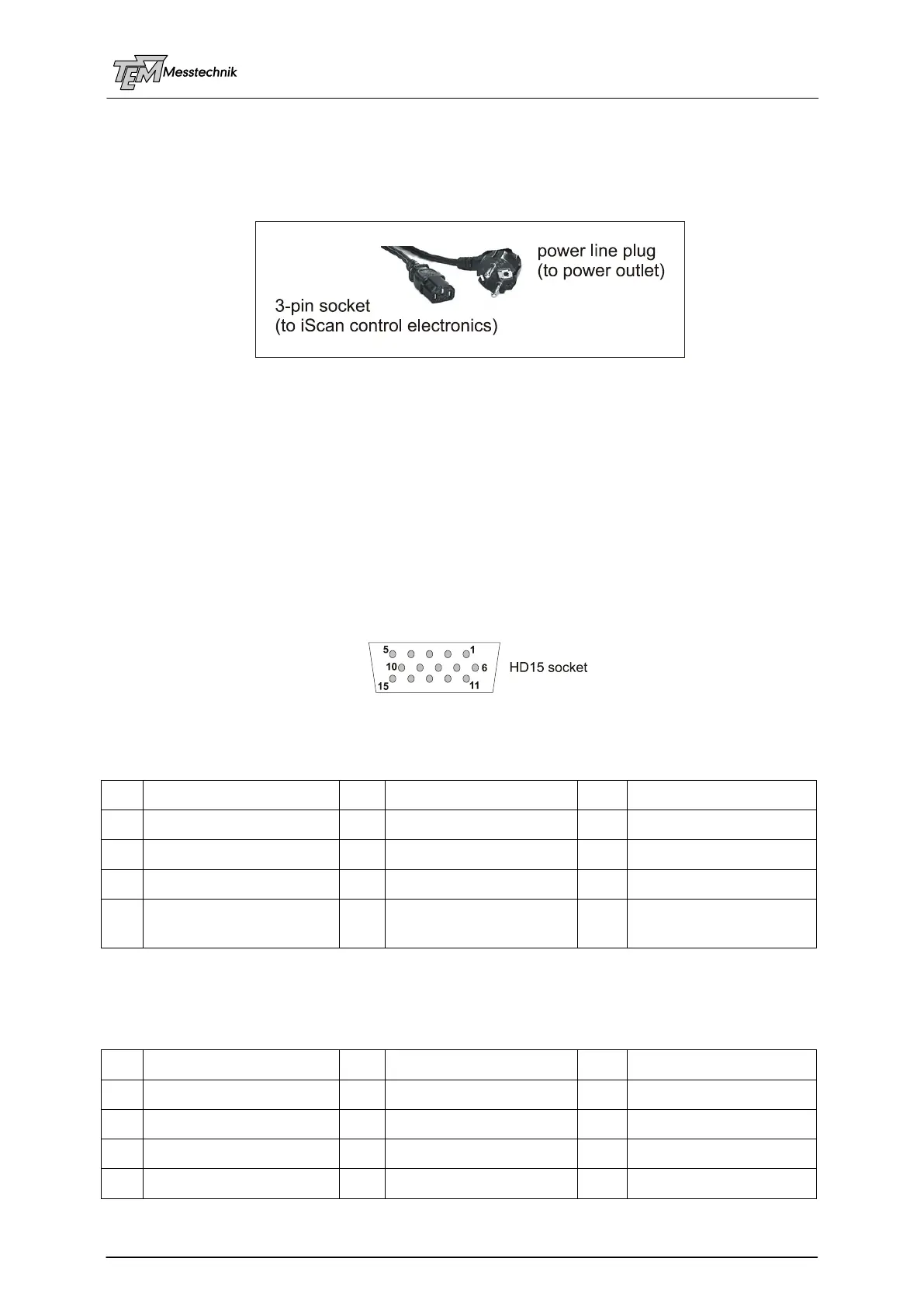
14.1.1 Mains power cable
Use the included power supply cable that provides proper grounding contact.
(The system may be delivered with country-specific mains power cables.)
14.1.2 Connection of the Detectors and Actuators
Notice! Only use the cable delivered with your system. Using standard cables
like those that are used for personal computers can lead to malfunction
or DAMAGE of electronic components: Many available cables have in-
ternal connections (common shielding of R,G,B) or some pins are not
connected.
NEVER use so-called VGA cables, they are not connected 1:1, and
they miss pins, especially pin 9, which is not used in VGA monitors.
14.1.2.14 PSD4D Connector ("PSD 1", "PSD 2",…):
Cable requirements: >= 0.09 mm², >= 20 V
14.1.2.15 Motor Actuator Connector ("M1", "M2", "M3", "M4"):
analog ground in
for differential inputs