Aligna
®
4D User Manual
18 / 84
A glass plate may cause interference effects due to multiple reflections between surfaces.
Because of this effect, glass plates with a small angle (wedge plates) are preferred.
However, they cause a (very small) angle deviation from the original direction.
In femtosecond laser applications the glass in the beam path may cause unwanted disper-
sion effects.
However, the problem of interference will not appear with fs laser applications: A pulse of
50 fs, e.g., has an optical length of approx 15 microns. The optical path length difference
between both reflections of a 1 mm glass plate is 100 times longer! Therefore, both reflect-
ed pulses would not interfere. here it is not necessary to use plates with an angle.
In this case thin plates (1...2 mm) are preferred. In most applications, the dispersion effects
can then be neglected.
It is very important to mount the glass plates without mechanical stress to avoid birefrin-
gence and deforming of the surfaces. Note: The reflected beam will define the reference ax-
is for the pointing stabilization. Any movement of this reference beam will directly lead to
movements of the main beam! Thus, a very thin glass thickness of less than 1 mm is not
recommended.
An uncovered glass plate at 45° splits approx. 1% of the beam for one polarization direction
(p-light) and 12 % for the other polarization direction (s-light). Both values differ by more
than an order of magnitude, which leads to strong unwanted polarization dependence of the
test beam intensity.
In most applications both values (1% and 12%) lead to test beam intensities which are far
above the necessary intensities of some microwatt. These test beam intensities have to be
reduced by strong optical filters, and they are lost for the main beam.
With horizontally polarized laser light, it is possible to get very low reflection rates by using
a reflection angle of around Brewster’s angle, approx. 57°. This angle will be slightly more
difficult to align compared to a 45° angle.
One (or both) surfaces can be AR (anti-reflex coated) for the target wavelength at 45°
deflection. However, it is not easy (and thus not cheap) to get high quality broadband AR
coatings with well-defined reflection grades, while HR mirrors are more easy to get.
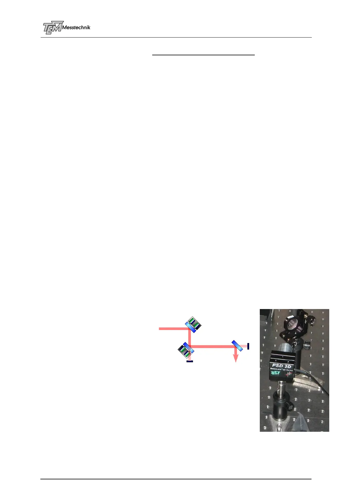
4.3.4 Setup 3: High Reflecting Mirror Acts as Beam Sampler
Because of these problems, it is usu-
ally better to use the transmission of a
HR (high reflecting) mirror as a beam
sampler. The transmissions are typi-
cally of the order of 1% down to
0.01%, which is by far enough in most
cases.
However, the polarization dependence of the transmitted beam can be
large. Especially high-bred mirrors for high-power or high energy fs pulse
lasers may have a polarization difference between s and p light by factor
of 100 or even 1000.
(Often HR mirrors for the target wavelength, in contrast to AR coated
substrates, are easier to get from stock.)
The distance between D1 and D2 defines the angle resolution.
In many applications, there are a lot of folding mirrors in the beam path.
One of the last mirrors before the experiment can be used as detection beam sampler for D2.