Aligna
®
4D User Manual
27 / 84
If the laser drifts or fluctuates, this setup gives an additional advantage: the whole beam path
between the mirrors also benefits from the stabilization. (Often additional optical components,
like telescopes, frequency doublers, etc. are located between the active mirrors. If in contrast
both mirrors are located near the target (as mentioned in former chapter) the 4D pointing at
the target will be stabilized as well, but the whole beam path before the second active mirror
will "see" the full laser drift and fluctuation.
In more general: The first active mirror should be located near the main source of drift (may be
located before or behind it). Thus, this drift is directly compensated near the source of drift,
and the whole beam path will be more stable (not only in the target path).
In many cases, the laser itself is the main source of drifts. (Then the first actuator should be
located close to the laser.). However sometimes another component may cause even larger
disturbance: motorized zoom objectives, dynamic delay lines, portal sleighs, etc. In these
cases the first active mirror should be located in the near of the strongest source of fluctuation.
The second active mirror and of course the detector should be located near the target.
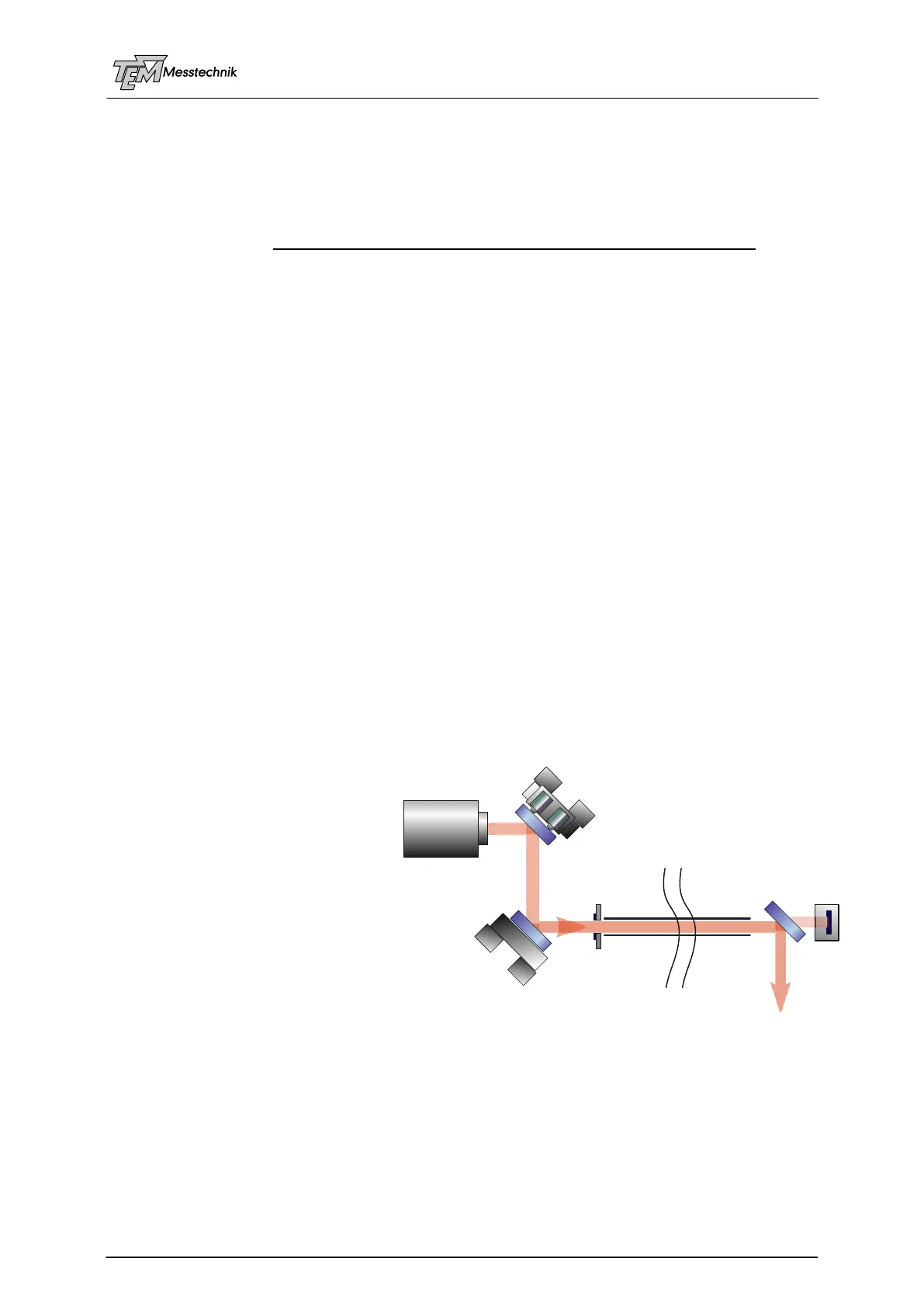
5.5 Auto-Alignment and 2D stabilization
In laser systems with long paths, the beam often is guided in a beam line tube (BLT). The
longer this beam line tube (and the thinner this tube is) the more difficult it is to align the beam
manually through this tube. (The BLT may be several 10 meters or even 100s meters long.)
Sometimes this tube is evacuated. In this case, alignment is even more difficult, because the
beam cannot be seen and manually aligned using paper screens or fluorescent plates.
In these cases, a fully automatical alignment through this beam line tube helps saving a lot of
time.
(Auto-Alignment of these systems is described in detail in another chapter. Here just the basic
principles are mentioned.)
For fulfilling this task, the Aligna system benefits from its matrix-based movements. By using
linear combinations of four motors (two 2D active mirrors), the beam can be turned around any
point along the beam path.
The basic steps are:
1. 2D-scanning of M2 (or M1), until
the tube entrance has been hit.
2. The beam will be 2D angle-
scanned around the mid position of
the tube entrance aperture, while
beam position at the tube entrance
is held fixed. This is done, until the
tube exit is hit, detected by the PSD
(or another detector).
For hitting the tube entrance, a so-
called "AimPD" is used. In principle
this is a simple photo detector (PD), located at the tube entrance. (Normally this detector is not
located in the center of the tube entrance, but at its border. However, it is also possible to use
a motorized PD, which is driven by a small motor into the optical axis for this pre-alignment
task. Alternatively, a flip mirror, or even a permanent beam sampling plate is inserted into the
beam path at the entrance of the BLT, reflecting a part of the main beam to the detector. The-
se "AimPDs" are described later in detail.)
If the beam now hits the AimPD, it automatically centers to this PD. Then the beam is moved
from the border of the tube to the middle of the tube.
2D System
with AutoAlignment
M1
M2
MoA
MoPiA
AimPD
BeamLine
Tube
PSD 2D
Laser
(or PSD 4D)