Aligna
®
4D User Manual
56 / 84
40 mirror mounts are used, the transformation of motor units to mirror angle movement will
differ by a factor of two, because of different dimensions.
It depends on the orientation of the mirror mount, whether a positive x (or y) motor movement
will cause a positive or negative beam angle movement.
In addition, if 45° mirror blocks or 45° piezo mounts are used, the scaling will differ by a factor
of sqrt(2) from the situation without these 45° mounts. These actuator-specific parameters can
be pulled out of the matrix to the motor-specific scaling parameters. Thus, the remaining OCL
is more or less a description of the optical setup and coupling effects, while the motor scale
values represent properties of the mirror mounts and of the motors. This simplifies the inter-
pretation of the OCL values.
In the example OCL these 45° mirror mounts are represented by the scaling values of “5.0”
and “7.0”, which approximately differ by sqrt(2).
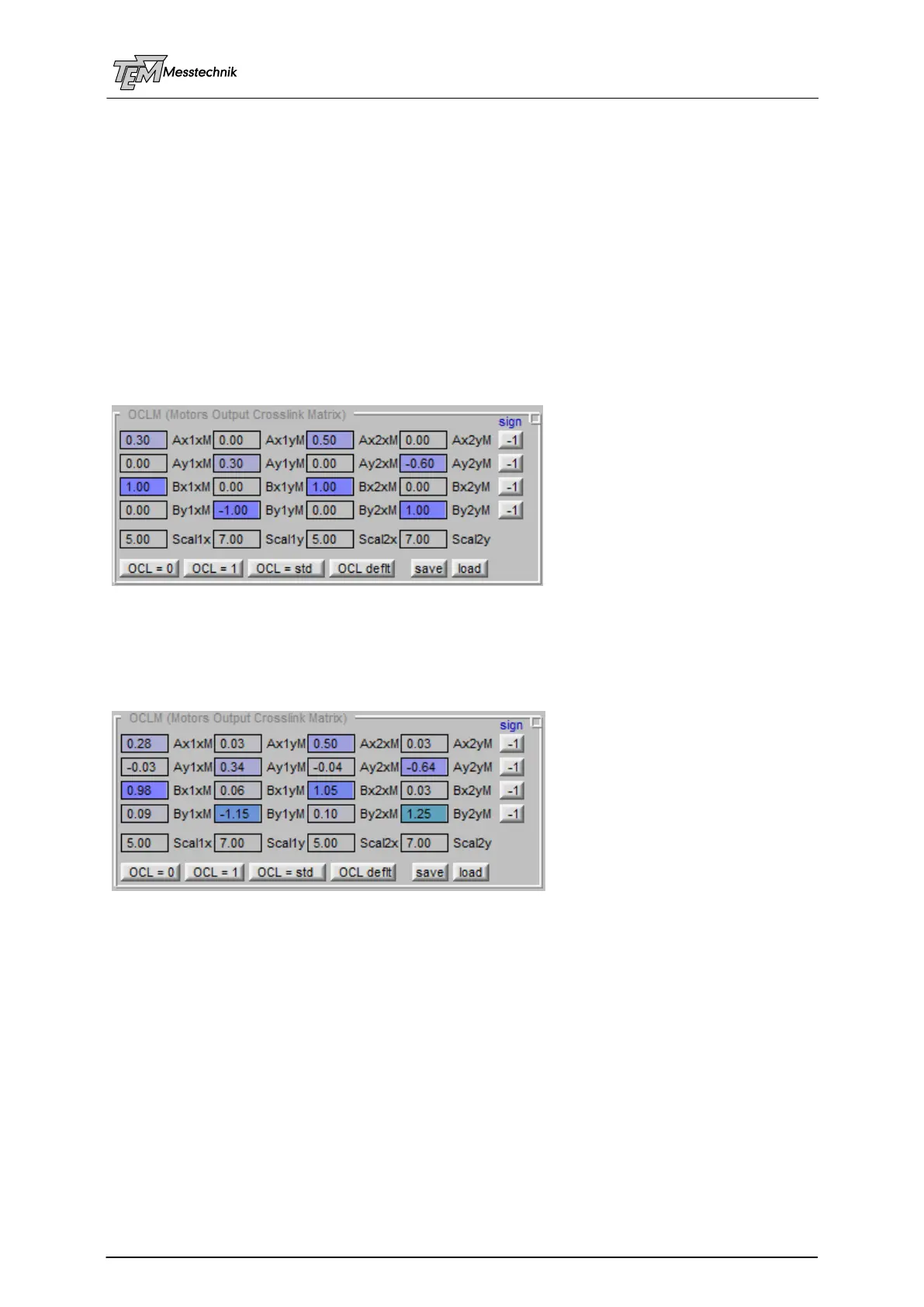
A default matrix of the sketched test setup may look as follows:
For example a beam position shift in x direction (“Bx”) will be performed by the same amounts
of motor 1x (coefficient “Bx1xM”=1) and motor 2x (coefficient “Bx2xM”=1). In this case, the
angle shift of both mirrors will cancel each other, which results in a position shift (without angle
movement).
After “Learning” of the matrix, it looks as follows:
You can see small deviations from the default matrix, and X/Y-coupling elements, which rep-
resent the deviation from “ideal” gimbal mounts, and other coupling and scaling effects.