HYDRAULICS
8J-36
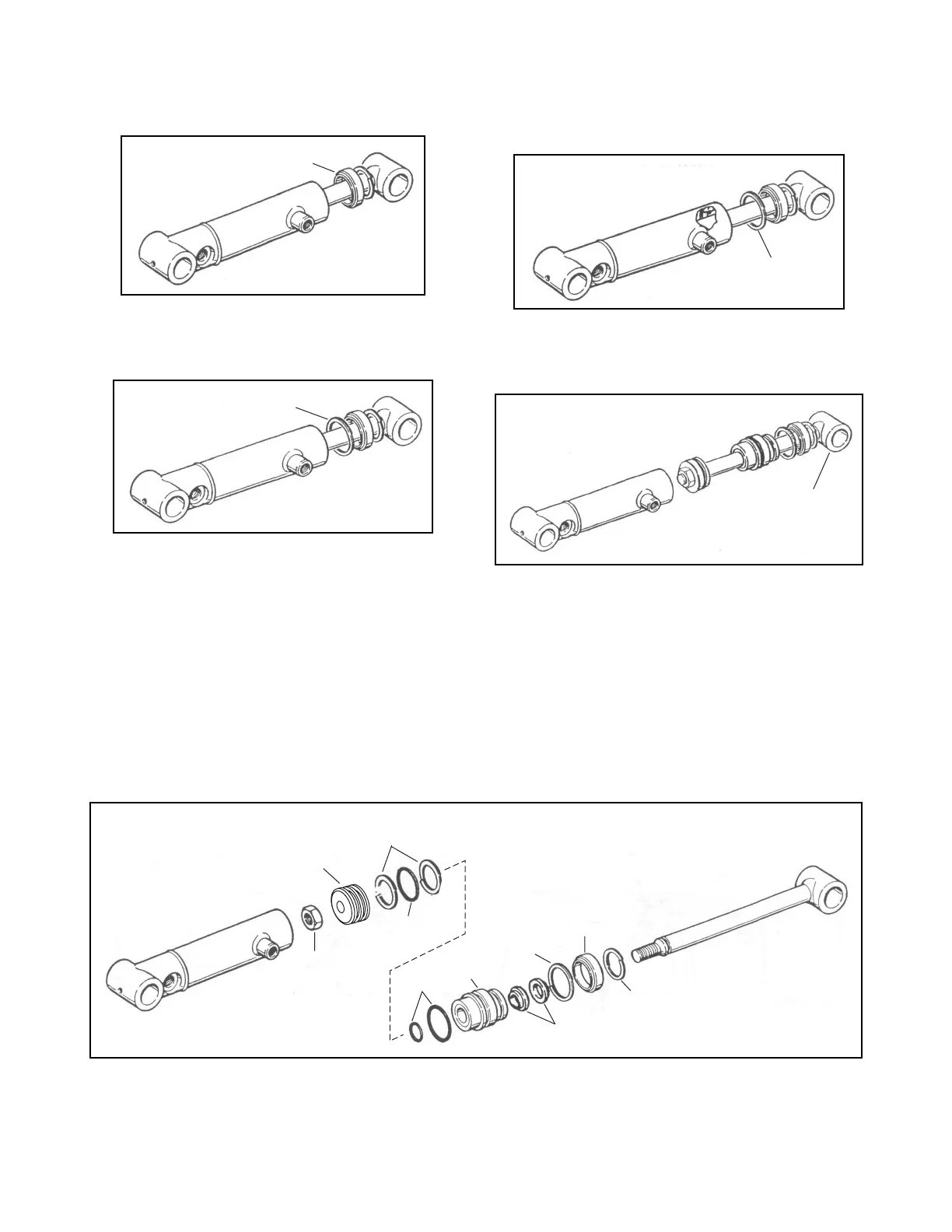
c. Remove the nylon spacer (Figure 8J-4).
Figure 8J-4. Nylon Spacer
d. Remove head lock ring from inside the cylinder
body (Figure 8J-5).
Figure 8J-5. Head Lock Ring
e. Remove sharp edges from the lock ring groove
(Figure 8J-6).
Figure 8J-6. Lock Ring Groove
f. Pull the rod assembly from the cylinder body
(Figure 8J-7).
Figure 8J-7. Rod Assembly
ASSEMBLY
1. Lightly lubricate o-rings, backup rings, and seals
with clean hydraulic oil.
2. Install seal kit as shown in Figure 8J-8.
NOTE:
Do not install rod o-ring at this time.
3. Lubricate all parts with clean hydraulic oil before
assembly.
Figure 8J-8. Lift Cylinder Assembly
Nylon Spacer
Lock Ring
Lock Ring
Groove
Rod
Assembly
Nut
Piston
O-Ring
Backup
Washers
O-Ring
Rod
Guide
Wiper
Lock
Ring
Lock
Ring
Spacer
 Loading...


