BRAKE SYSTEM
5C-6
Disassembly
1. Using a suitable jack, lift the front wheels off the
ground. Support the tractor with jack stands.
2. Release the parking brake.
NOTE:
Removing the wheel allows better access to the
brake assembly.
3. Remove the return spring (Figure 5C-2).
4. Remove the cable and yoke from the actuating
lever.
5. Remove four bolts from the brake bracket.
6. Remove the brake bracket from the caliper.
7. Remove the brake pads and support plates from
the caliper.
8. Remove the spring retainer and actuating lever.
Inspection and Cleaning
1. Remove brake dust, dirt, and debris from the
brake assembly.
2. Inspect the brake pads and support plates for
wear and distortion. Replace as necessary.
3. Inspect the spring retainer and actuating lever and
return springs for wear and distortion. Replace as
necessary.
4. Inspect the cables and cable mounting for wear
and damage. Replace as necessary.
5. Inspect the brake disc and hub for grooves,
excessive wear, and damage. Replace the hub
and brake disc as necessary.
Assembly
1. Assemble the caliper, actuating lever, spring
retainer, pads, and support plate (Figure 5C-2).
2. Install the caliper assembly over the brake disc
and secure with the brake bracket and four bolts.
NOTE:
If the brake has been adjusted in the past, it may
be necessary to adjust the brake cables down for
installation of the cable and yoke on the actuating
lever.
3. Install the brake cable and return spring on the
actuating lever.
4. Adjust the parking brake as needed.
5. Lift the tractor and remove the jack stands.
Adjustment
1. Check the brake-actuating lever. The lever should
just touch the inner support plate.
2. Check the brake pedal free travel (Figure 5C-2).
The pedal free travel should be approximately
1.5 in (38 mm).
3. Use the cable nuts to adjust free travel and actuat-
ing lever position.
4. Repeat the procedure for the other side.
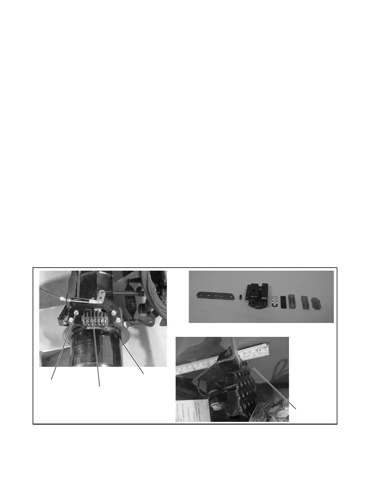
Figure 5C-2. Brake Assembly and Adjustment
Caliper
Brake Disc
and Hub
Brake
Bracket
Brake Disc
and Hub
Brake Caliper Assembly
Brake Pedal
Free Travel
 Loading...


