2-31
2
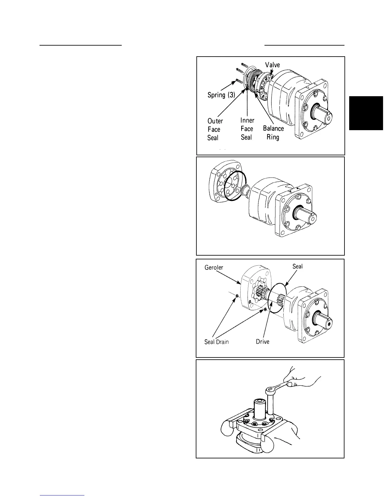
6 Remove the two balance springs, balance ring and
the valve (fig. C255). Remove the inner and outer face
seal from the balbance ring.
DRIVE MOTOR 2.12
Disassembly (cont’d)
10 Remove the geroler drive and seal from the bearing
housing (fig. C250)
11 Turn the bearing housing over in the vise and
remove the cap screws (fig. C250) On re-assembly,
torque the cap screws 21ft/lbs. (28.5 NM)
12 Remove the retainer plate from the bearing hous-
ing. Remove the back-up washer and quad ring from the
retainer plate.
8 remove the geroler and lock assembly (fig.C257).
Keep the rollers and linner geroler in the outer geroler
ring.
9 Remove the drain seals from each side of the geroler
assembly. (fig. C257)
7 Remove the valve plate, seal and the valve drive
(fig. C256).
C255
C257
C250
C256