2-36
2
DRIVE MOTOR 2.12
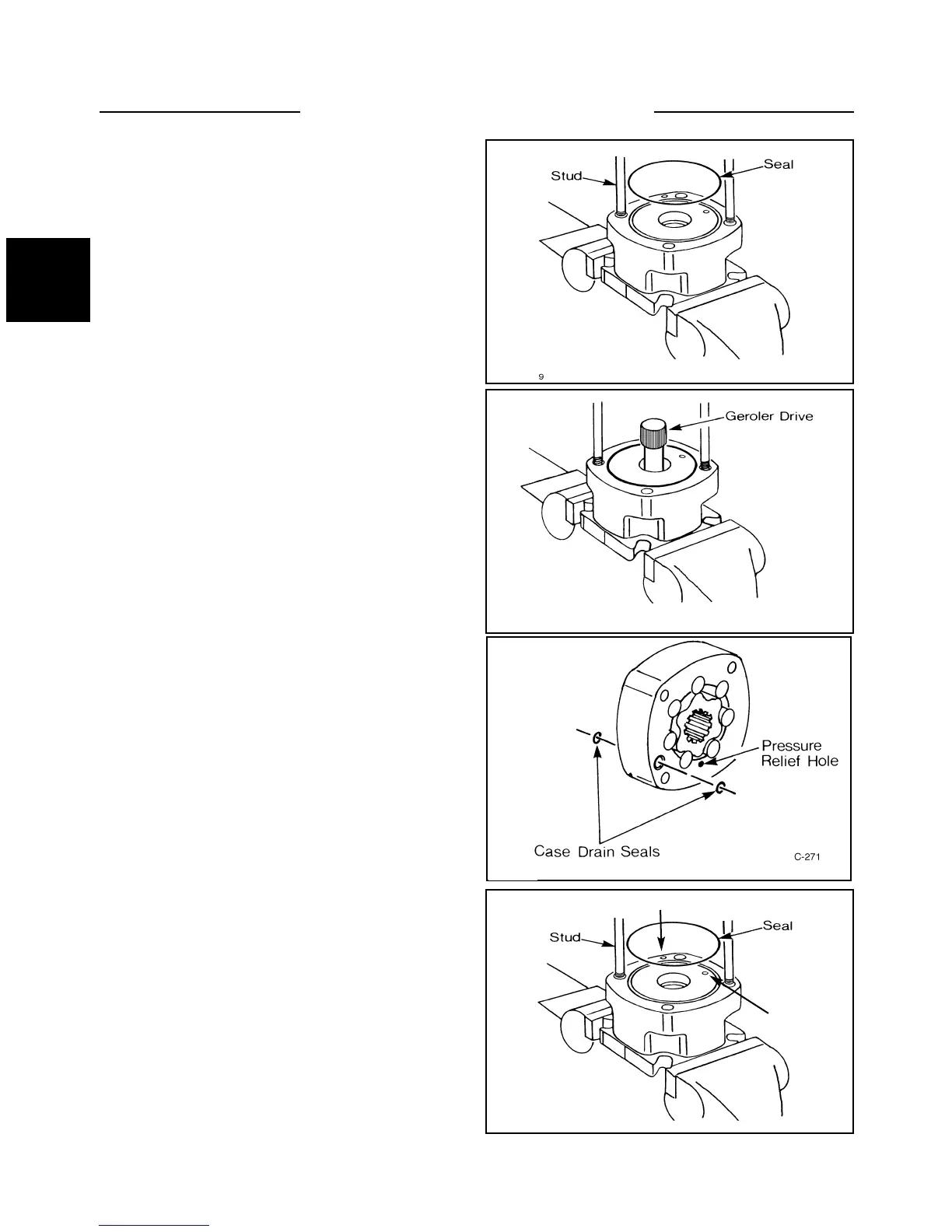
9 If available, install two studs in the housing (fig.
C269) to assist in alignment of parts during assembly.
10 Apply a light film of light grease on the housing seal
and install the seal in the housing. (fig. C269)
Assembly (cont’d)
13 Align the case drain and pressure relief hole in the
geroler assembly with the matching holes in the bearing
housing (fig. C271, C270). Install the geroler assembly
on the bearing housing.
12 Apply light grease to the two case drain seals and
install the seals on both sides of the geroler assembly
(fig.C271) in the drain hole grooves.
11 Install the geroler drive shaft in the housing (fig.
C270). Install the longer splined end of the drive shaft in
the housing.
C269
C270
C271
C270
Drain hole
Pressure
relief hole