5-114
dummyheaddummyhead
FUEL SYSTEM
CIRCUIT INSPECTION
1. No.8 Fuse (10 A) inspection
Turn the combination switch OFF.
Check for blown No.8 fuse.
Is the fuse blown?
YES – Replace the blown fuse and check for
short in the main wire harness or incorrect
load by referring to the fuse load chart
(page 4-16).
NO – GO TO STEP 2.
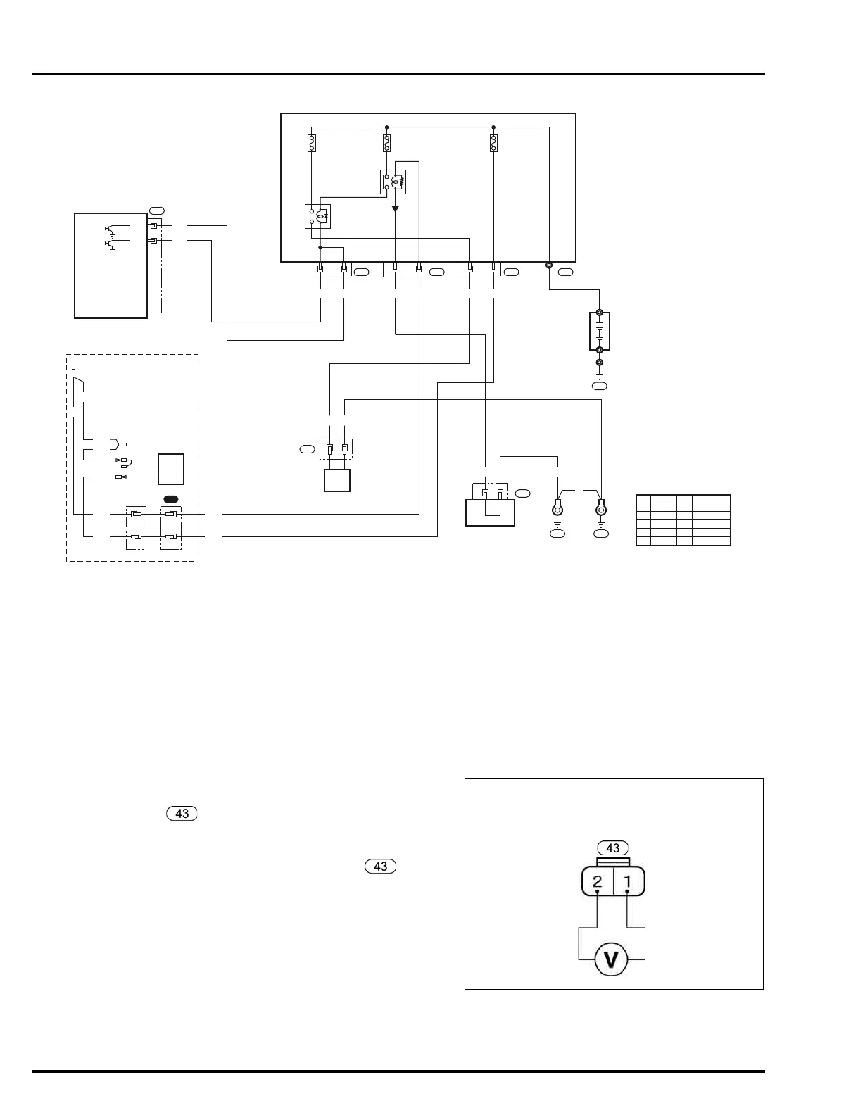
2. Fuel pump power/ground line open circuit
inspection
Turn the combination switch OFF and disconnect
the fuel pump (High pressure side) 2P connector
.
Turn the combination switch ON.
Measure the battery voltage between the fuel pump
(High pressure side) 2P connector main wire
harness side No.2 (Blue/Red) terminal and No.1
(Black) terminal.
Is there battery voltage for a few seconds?
YES – Replace the fuel pump (High pressure
side) with a new one and recheck.
NO – GO TO STEP 3.
BATTERY
Bl/Y
W/Bl
54 94 54
Bu/R
14 13
LgFLR1
FLR2
ECM
Lg
2
24 23
1
Bl
JOINT CONNECTOR 1
FUEL PUMP
43
12
Bu
2
Bl/Y
W/Bl
COMBINATION
SWITCH
MAIN
RELAY
FUSE/RELAY
JUNCTION BOX
No.5 FUSE
(10A)
No.4 FUSE
(30A)
No.8 FUSE
(10A)
FUEL
PUMP
RELAY
Bl/Y
W/Bl
1
LOAD
BAT
Bl/Y
W/Bl
Bl/Y
Bl/Y
Bl/Y
Bl/Y
OPTION
2
Lg Lg Bl Bl/Y Bu/R W/Bl
Bl BlBl
29
28 27 T4
GND3GND1
11
GND6
Bl
Y
Bu
G
R
W
Black
Yellow
Blue
Green
Red
White
Br
O
Lb
Lg
P
Gr
Brown
Orange
Light blue
Light green
Pink
Gray
FUEL PUMP (HIGH PRESSURE SIDE)
2P CONNECTOR
MAIN WIRE HARNESS SIDE
GND3
(Black)
FUEL PUMP
(Blue/Red)
 Loading...