Pre-setup Preparation
NET-G3A Operator’s Manual
2-12
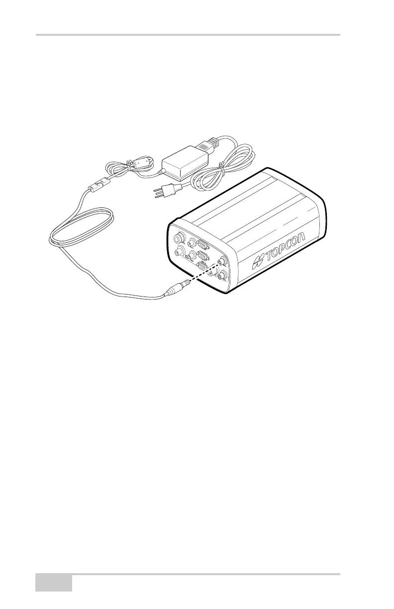
2. Connect the SAE connectors on the power adapter cable and
power supply unit.
3. Connect the power adapter cable to a PWR port on the receiver’s
rear panel.
4. Plug the power supply to an available outlet.
Figure 2-5. Connecting the Net-G3 to a Power Source
Checking Power Status
You can check the receiver’s power status using the PWR LEDs or
available Topcon software. The power LEDs on the receiver indicate
the following power status:
• Solid Green – power within the acceptable range (6–28 V DC) is
present on this PWR port and is being used to power the receiver.
The corresponding backup battery is fully charged.
• Solid Yellow – power within the acceptable range (6–28 V DC) is
present on this PWR port but is not being used to power the
receiver.
• Solid Red – either a power failure has occurred (with connected
power source) or power is not present on this PWR port. For
details, see “Powering Problems” on page 5-2.
To grounded
outlet
Net-G3A_OM_Book.book Page 12 Thursday, May 14, 2009 8:49 AM