Greensmaster 3250--DHydraulic System Page 4 -- 76
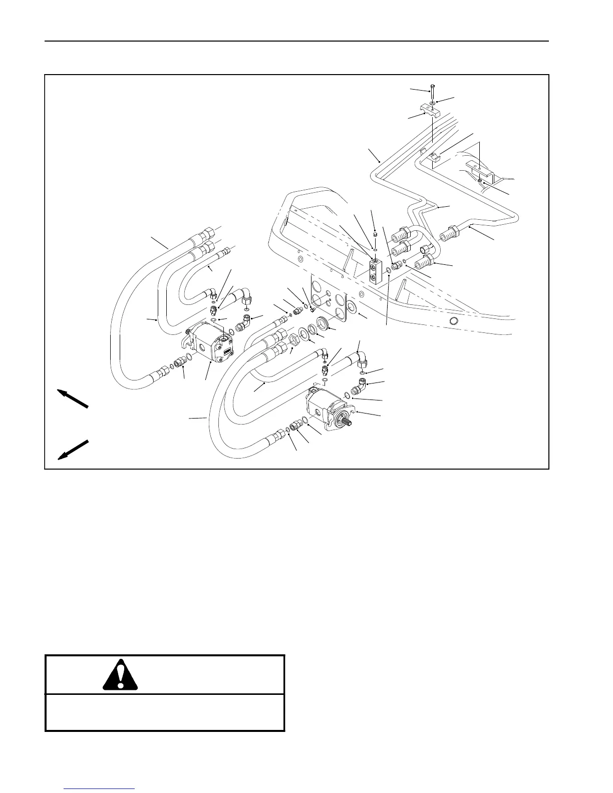
Cutting Reel Motors
1. Cap screw
2. Flat washer
3. Tube clamp
4. Lock nut
5. Plug
6. 90
o
Hydraulic fitting
7. Hydraulic fitting
8. Hydraulic fitting
9. O--ring
10. Bulkhead nut
11. Washer
12. Spacer
13. Reel motor
14. Hose assembly
15. Hose assembly
16. Hydraulic fitting
17. Hose assembly
18. T--block
19. Cap screw
20. Hydraulic tube
21. Hydraulic tube
22. Hydraulic tube
23. Hydraulic tube
24. Rubber grommet
25. O--ring
26. O--ring
27. O--ring
28. O--ring
29. O--ring
30. O--ring
Figure 50
4
20
23
22
21
16
5
18
15
14
17
7
6
8
13
7
12
19
24
10
11
11
7
17
6
13
8
14
15
1
3
2
3
25
26
27
28
28
27
30
29
30
29
9
FRONT REEL MOTORS
FRONT
RIGHT
Removal (Figs. 50 and 51)
1. Park the machine on a level surface, engage the
parking brake, lower the cutting units and stop the en-
gine. Remove key from the ignition switch.
CAUTION
Before continuing further, read and become fa-
miliar with General Precautions for Removing
and Installing Hydraulic System Components.
2. Label hydraulic hoses for assembly purposes.
3. Disconnect hydraulic hoses from fittings on the reel
motor. Allow hoses to drain into a suitable container.
Caporplughosesandmotorfittingstopreventcontami-
nation.
4. Loosen two (2) cap screws that secure the hydraulic
reel motor to t he cutting unit side plate. Rotate motor
clockwise and remove motor from cutting unit.
NOTE: Thepositionofhydraulicfittings on the reel mo-
tor is critical to properly connecting hydraulic hoses.

 Loading...


