Greensmaster 3250--D Page 3 -- 1 5 Diesel Engine
Engine Removal (Fig. 12)
1. Park machine on alevelsurface,lower cutting units,
stop engine, engage parking brake and remove key
from the ignition switch.
CAUTION
The engine, radiator, exhaust system and hy-
draulic system may be hot. To avoid possible in-
jury,allowmachinetocoolbeforeworkingonthe
engine.
2. Close fuel shut--off valve on fuel tank.
3. Remove air cleaner and air intake hose from ma-
chine (see Air Cleaner in this section).
4. Remove radiator from machine (see Radiator in this
section).
5. Remove exhaust system from machine (see Ex-
haust System in this section).
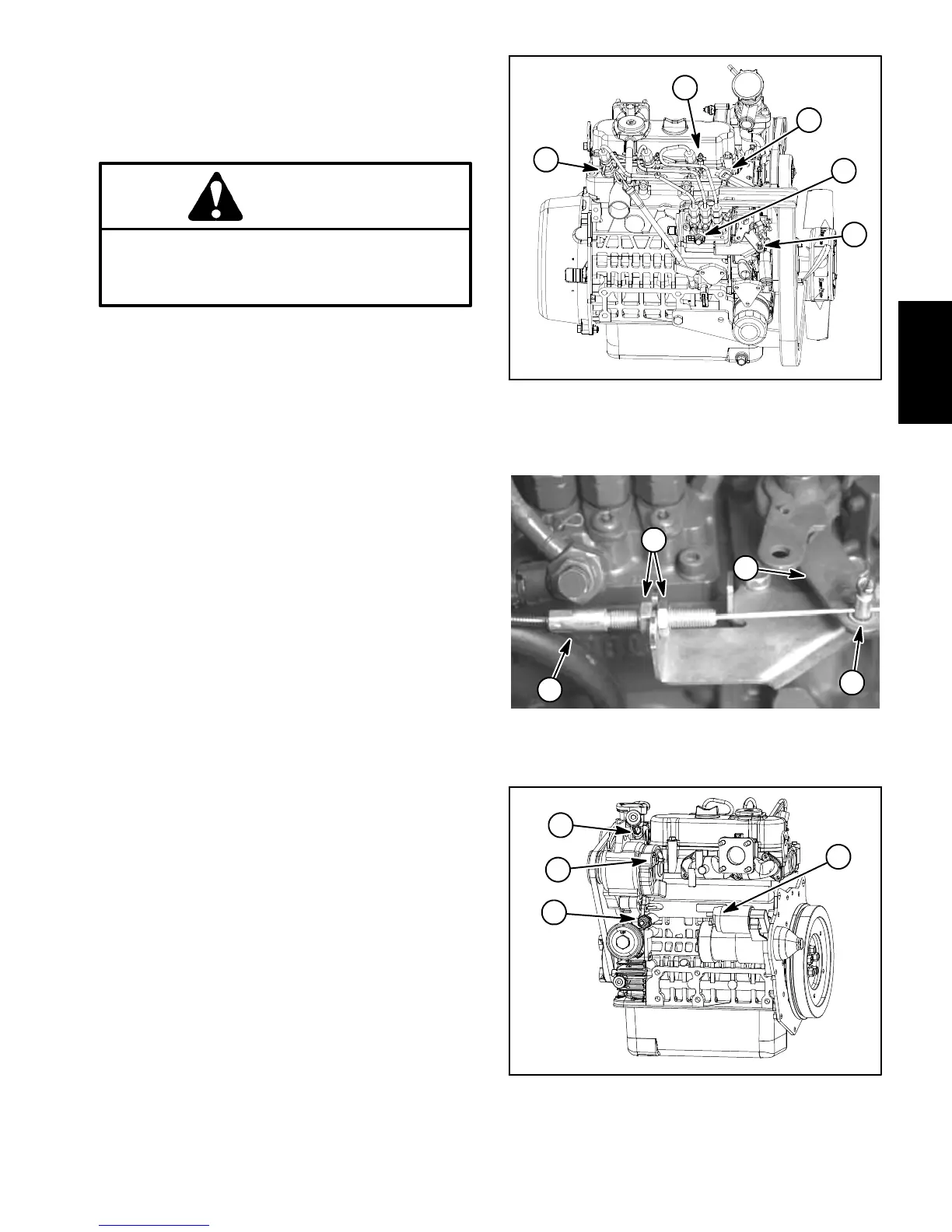
6. Disconnect fuel supply hose from the injector pump
andfuelreturnhosefromthe#3 injector (Fig. 13). Drain
any fuel trapped in the hoses into a suitable container.
Plughosesandpositionthemawayfromengineassem-
bly.
7. Loosenscrewthatsecuresthethrottlecabletoswiv-
el on injector pump speed control lever. Disconnect
cable from swivel and cable bracket (Fig. 14). Position
cable away from engine.
8. Disconnect wire harness c onnectors from engine
components:
NOTE: Beforedisconnectingwireharnessconnectors,
label all electrical leads for assembly purposes.
A. Negative battery cable (item 4) and wireharness
ground (item 2) that are secured to the engine at the
lift hook above the bell housing.
B. Fuel solenoid (Fig. 13).
C. Glow plug bus (Fig. 13).
D. Temperature sender (Fig. 15).
E. Alternator connector and stud (Fig. 15).
F. Starter motor solenoid and fusible link harness
(Fig. 15).
G. Oil pressure switch (near oil filter) (Fig. 15).
Figure 13
1. Fuel return fitting
2. Throttle cable swivel
3. Fuel supply fitting
4. Glow plug bus
5. Fuel solenoid
1
2
4
3
5
Figure 14
1. Throttle cable
2. Speed control lever
3. Cable jam nut
4. Throttle cable swivel
4
2
1
3
Figure 15
1. Temperature sender
2. Alternator stud
3. Oil pressure switch
4. Starter solenoid
1
2
3
4
Engine
Diesel

 Loading...


