Greensmaster 3250--DHydraulic System Page 4 -- 82
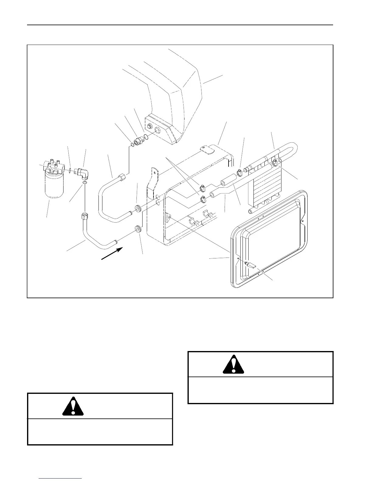
Oil Cooler (If Equipped)
1. Oil cooler
2. Lower formed hose
3. Upper formed hose
4. Grommet (2 used)
5. Hose clamp (4 used)
6. Hydraulic tube
7. Hydraulic tube
8. Hydraulic straight fitting
9. 90
o
hydraulic fitting
10. O--ring
11. O--ring
12. Radiator support
13. Hydraulic filter
14. Hydraulic tank
15. Radiator screen
16. Latch (2 used)
Figure 57
OIL FLOW
2
3
6
8
9
10
11
1
5
7
12
4
4
5
5
10
11
13
14
15
16
Removal (Fig. 57)
1. Park the machine on a level surface, engage the
parking brake, lower the cutting units and stop the en-
gine. Remove key from the ignition switch.
CAUTION
Before continuing further, read and become fa-
miliar with General Precautions for Removing
and Installing Hydraulic System Components.
CAUTION
The radiator and oil cooler may be hot. To avoid
possible burns, allow the engine and cooling
systemsto cool before workingon the oil cooler.
2. Remove radiator screen from radiator support.
3. Clamp upper and lower formed hoses (items 3 and
2) to prevent draining of the hydraulic system and tank.

 Loading...


