Greensmaster 3250--D
Page 5 -- 21
Electrical System
Joystick Raise and Lower Switches
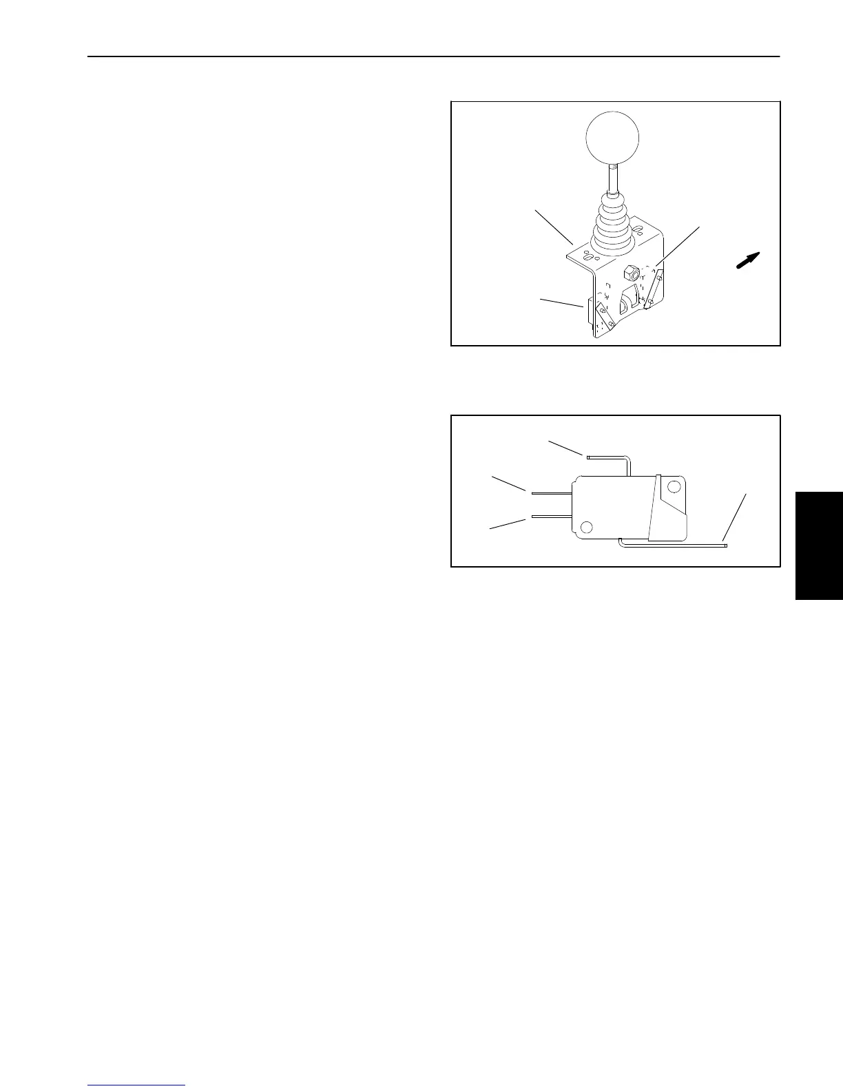
Thejoystickraiseandlowerswitchesarelocated onthe
joystickassemblythatisattachedtothecontrolconsole.
Therearswitchisusedtolowerthecuttingunitsandthe
front switch to raise them (Fig. 22). The switches are
identical and are shown in Figure 23.
Testing
1. Park machine on level surface, lower cutting units,
stop engine, apply parking brake and remove key from
ignition switch.
2. Remove console cover from console assembly to
gain access to joystick switches.
3. Make sureignitionswitchisin theOFFposition.Dis-
connect wire harness connectors from joystick
switches.
4. Check the continuity of the raise switch by connect-
ing a multimeter (ohms setting) across the switch con-
nector terminals as follows:
A. Withthejoystickintheneutralposition,continuity
should only exist between the common and NC ter-
minals.
B. With the joystick in the raise position, continuity
should only exist between the common and NO ter-
minals.
5. Check the continuity of the lower switch by connect-
ing a multimeter (ohms setting) across the switch con-
nector terminals as follows:
A. Withthejoystickintheneutralposition,continuity
should only exist between the common and NC ter-
minals.
B. With the joystick in the lower position, continuity
should only exist between the common and NO ter-
minals.
6. Replace joystick switch if necessary.
7. After switch testing is completed, connect the har-
nessconnectorstothejoystickswitches.Installconsole
cover.
1. Joystick assembly
2. Raise switch
3. Lower switch
Figure 22
1
2
3
FRONT
1. Common terminal
2. NO terminal
3. NC terminal
4. Switch lever
Figure 23
1
2
3
4
Electrical
System

 Loading...


