Greensmaster 3250--D Hydraulic SystemPage 4 -- 3 7
Procedure for Gear Pump (Rear Section) Flow
Test
1. Make sure hydraulic oil is at normal operating tem-
peraturebyoperatingthemachineforapproximatelyten
(10) minutes.
2. Parkmachineonalevelsurfacewiththecuttingunits
lowered. Make sure engine is off and the parking brake
is engaged. Make sure the hydraulic tank is full.
CAUTION
Before continuing further, read and become fa-
miliar with Precautions for Hydraulic Testing.
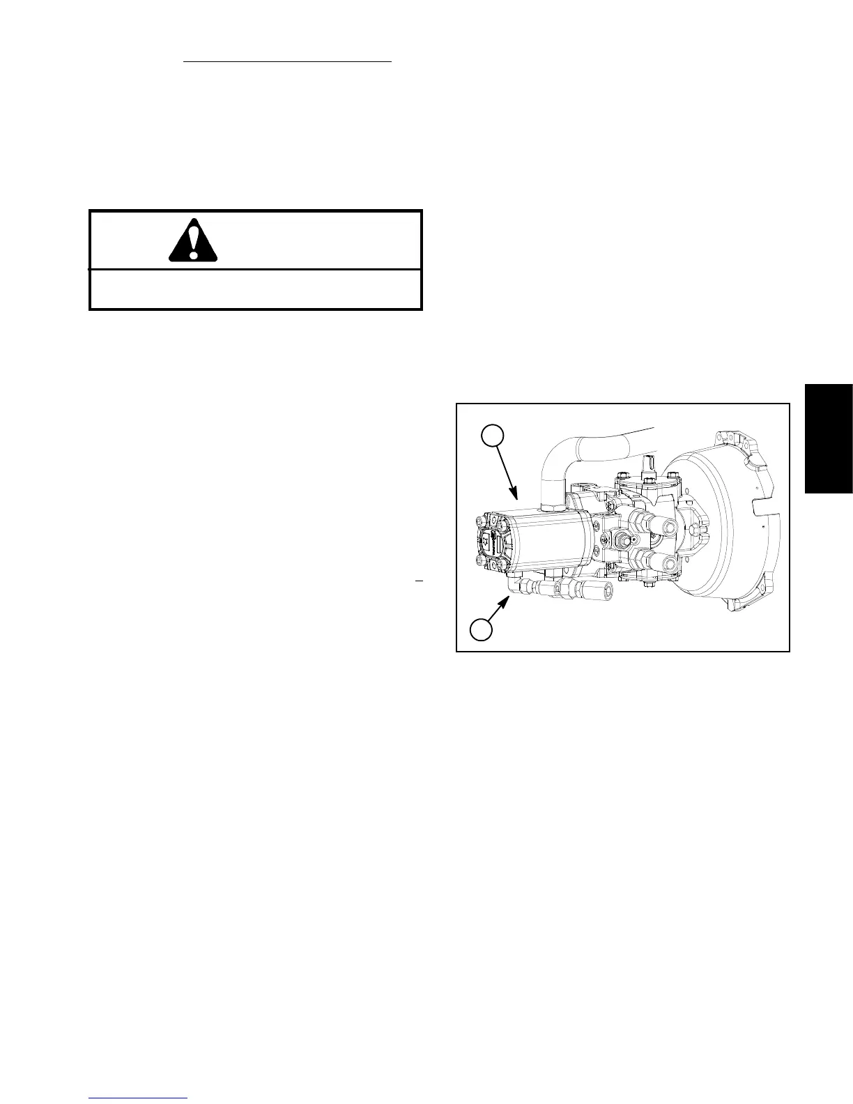
3. Thoroughly clean junction of hydraulic hose and the
hydraulic fitting in the rear gear pump section (F ig. 21).
This hose leads to port P in the steering valve.
4. Disconnect the hose from the fitting in the rear gear
pump section.
5. Install tester with pressure gauge and flow meter in
series with the gear pump fitting and the disconnected
hose. Make sure flow control valve on the tester is
fully open.
6. Makesurethattractionpedalandjoystickcontrolare
in neutral and the parking brake is engaged.
7. Start engine and operate at high idle speed (2710 +
50 RPM).
IMPORTANT: Do not fully restrict oil f low through
tester. In this test, the flow tester is positioned be-
fore the circuit relief valve. Gear pump damage can
occur if the oil flow is fully restricted.
8. Watchtesterflowandpressuregaugecarefullywhile
slowly closing the flow control valve on the tester until
the pressure gauge reads 800PSI(55bar).
9. Flow gauge reading for a rear gear pump section in
good condition should be approximately 3.6 GPM (13.6
LPM). Record test results.
10.Open control valve on tester and shut off engine.
11.If flow was less than 3.1 GPM (11.7 LPM) or a pres-
sure of 800PSI(55bar)cannot be obtained, check for
restrictioninthepump intake line.Iflineisnotrestricted,
remove gear pump and repair or replace as necessary.
NOTE: Implement Relief Valve Pressure and Lower
Cutting Units Relief Valve (R2) Pressure can be mea-
sured with tester positioned as described in this check
(see Implement Relief Valve Pressure Test and Lower
CuttingUnitsReliefValve(R2)PressureTestinthissec -
tion).
12.After testing is complete, disconnect tester from the
gearpump fittingandhose.Reconnect hoseto thegear
pump fitt ing.
1. Gear pump 2. Rear section fitting
Figure 21
2
1
Hydraulic
System

 Loading...


