Greensmaster 3250--DPage 3 -- 18Diesel Engine
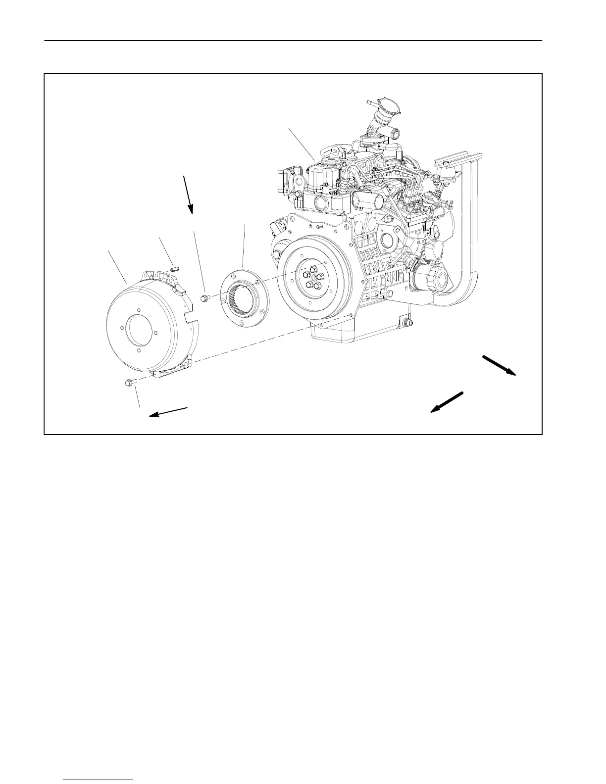
Engine Bell Housing
Figure 17
1. Engine
2. Flange head screw (5 used)
3. Bell housing
4. Coupling flange
5. Flange head screw (4 used)
6. Spring pin
FRONT
RIGHT
5
3
4
2
1
6
17 to 21 ft--lb
(23to28N--m)
Loctite #242
17 to 21 ft--lb
(23to28N--m)
Loctite #242
Removal (Fig. 17)
NOTE: The hydraulic pump assembly needs to be re-
moved from engine before bell housing and coupling
flange can be removed.
1. Ifengineisinmachine,supportenginefrombelowto
preventitfromshifting.Removehydraulicpumpassem-
bly(seePiston(Traction) Pump Removal in the Service
and Repairs section of Chapter 4 -- Hydraulic System).
2. As necessary, remove bell housing and coupling
flange from engine using Figure 17 as a guide.
Installation (Fig. 17)
1. If coupling flange was removed from engine fly-
wheel, position flange to flywheel and align mounting
holes. Apply Loctite #242 to threads of flange head
screws(item2). Securecouplingflangetoflywheelwith
five(5)flangeheadscrews.Tightenscrewsinastarpat-
tern to a torque 17 to 21 ft--lb (23 to 28 N--m).
2. Ifbellhousingwasremovedfromengine,makesure
that spring pin is secure in upper hole of bell housing.
Apply Loctite #242 to threads of flange head screws
(item 5). Position bell housing to flywheel plate and se-
curewith five (5) flange head screws.Tighten screws in
a star pattern to a torque 17 to 21 ft--lb (23 to 28 N--m).
3. If engine is in machine, install hydraulic pump as-
sembly (see Piston (Traction) Pump Installation in the
Service and Repairs section of Chapter 4 -- Hydraulic
System).

 Loading...


