Greensmaster 3250--DGroomer Page 8 -- 12
Grooming Reel Bearing Replacement
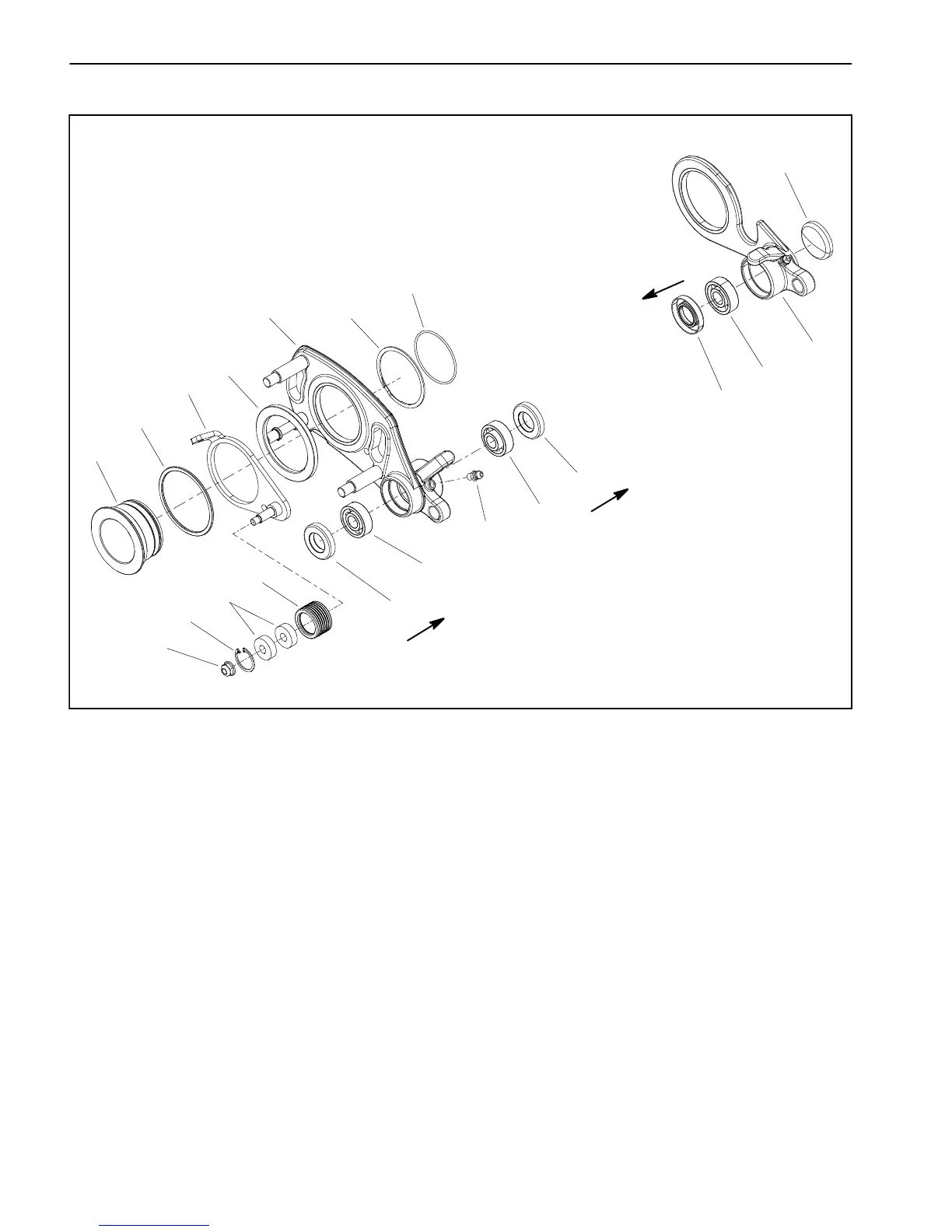
Figure 11
1. Pivot hub
2. Spacer
3. Idler bracket
4. Spacer
5. Drive plate (cutting unit RH side)
6. O--ring
7. Retaining ring
8. Grease fitting
9. Bearing
10. Seal
11. Idler pulley
12. Lock nut
13. Bearing
14. Retaining ring
15. Support plate (cutting unit LH side)
16. Plug
Seal lip
(toward center of
cutting unit)
12
11
10
9
5
3
4
2
1
7
8
6
10
9
13
14
9
10
15
16
Seal lip
(toward center of
cutting unit)
Seal lip
(toward center of
cutting unit)
NOTE: The groomer reel drive is located on the oppo-
sitesideofthecuttingunitfromthehydrauliccuttingreel
motor.
Bearing Removal
1. Remove the cutting unitfromthemachine and place
cutting unit on a flat work area.
2. Remove front roller, grooming reel and drive plate
assembly from right side of cutting unit (see Grooming
Reel Removal in this section).
3. Remove groomer support plate assembly from side
of cutting unit:
A. Remove two (2) socket head screws and lock
nutsthatsecuremotormounttocuttingunit(Fig.12).
Remove motor mount from cutting unit.
B. Remove lock nut and spring washer that secure
LHgroomerarmliftrodtosupportplate(Fig.13).Re-
move support plate from cutting unit.

 Loading...


