Greensmaster 3250--DPage 3 -- 16Diesel Engine
CAUTION
Support the hydraulic pump assembly when re-
moving its supporting fasteners to prevent it
from falling and causing damage or personal in-
jury.
9. Support hydraulic pump assembly to prevent it from
moving during engine removal.
10.Removetwo(2)capscrewsandflatwashersthatse-
curehydraulicpumpassemblytobellhousingonengine
(Fig. 16).
CAUTION
When removing engine assembly, make sure lift
or hoist can safely support 190 lbs (86 kg).
11.Attach a suitable lift o r hoist to engine. Support en-
gine with lift or hoist to prevent engine from shifting or
moving.
12.Remove fasteners that secure engine to machine:
A. Remove cap screw, mount spacer, washers and
flangenutthatsecureenginesupport(item19)toen-
gine mount.
B. Remove two (2) cap screws (item 12) and lock
nuts(item22)thatsecurerearengineplatetoengine
mount (item 6).
IMPORTANT: Make sure to not damage the engine,
fuel hoses, hydraulic lines, electrical harness or
other parts while removing the engine. Also, make
sure that hydraulic pump assembly does not shift
location during engine removal.
13.Slowlymovetheengineassemblyawayfromthehy-
draulic pump assembly to allow the pump coupling to
slide out of the engine coupling flange (Fig. 16). Once
the engine has cleared the pump coupling, carefully re-
move the engine from the machine.
14.If necessary, remove engine support (item 19) from
engine.
Engine Installation (Fig. 12)
1. Make sure that all removed engine components are
correctly installed to the engine.
2. If engine support (item 19) was removed from en-
gine, secure support to engine with removed fasteners.
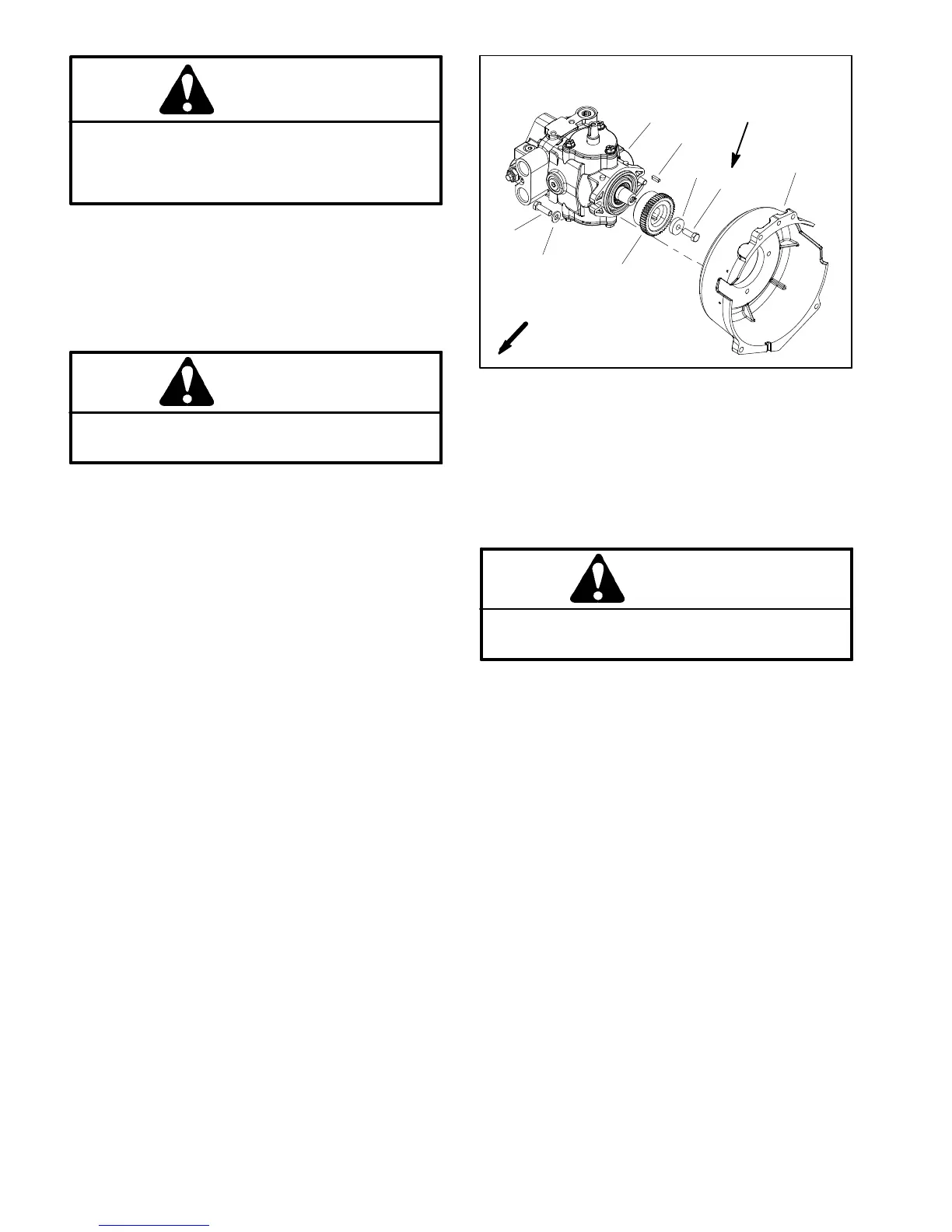
1. Piston pump
2. Cap screw (2 used)
3. Flat washer (2 used)
4. Coupling
5. Cap screw
6. Spacer
7. Bell housing
8. Key
Figure 16
3
1
4
2
6
5
7
8
27 to 33 ft--lb
(37to44N--m)
FRONT
Loctite #242
3. Makesurethathydraulicpumpassemblyiswellsup-
ported to prevent it from moving during engine Installa-
tion.
CAUTION
When installing engine assembly, make sure lift
or hoist can safely support 190 lbs (86 kg).
4. Attach a suitable lift or hoist to engine.
IMPORTANT: Make sure to not damage the engine,
fuel hoses, hydraulic lines, electrical harness or
other parts while installing the engine. Also, make
sure that hydraulic pump assembly does not shift
location during engine installation.
5. Slowly move the engine assembly toward the hy-
draulic pump assembly to allow the pump coupling to
slide into the engine coupling flange (Fig. 16).
6. Secure hydraulic pump assembly to bell housing on
engine with two (2) cap screws and flat washers (Fig.
16).
7. Secure engine to machine:
A. Secureenginesupport(item19)toenginemount
with cap screw, mount spacer, washers and flange
nut.
B. Securerearengineplatetoenginemount(item6)
withtwo(2) cap screws (item12)andlock nuts (item
22).

 Loading...


