Greensmaster 3250--D Hydraulic SystemPage 4 -- 7 9
IMPORTANT: Mark therelativepositions of the gear
teeth and the bearing blocks so they can be re-
assembled in the same position. Do not touch the
gearsurfacesasresidueonhandsmaybecorrosive
to gear finish.
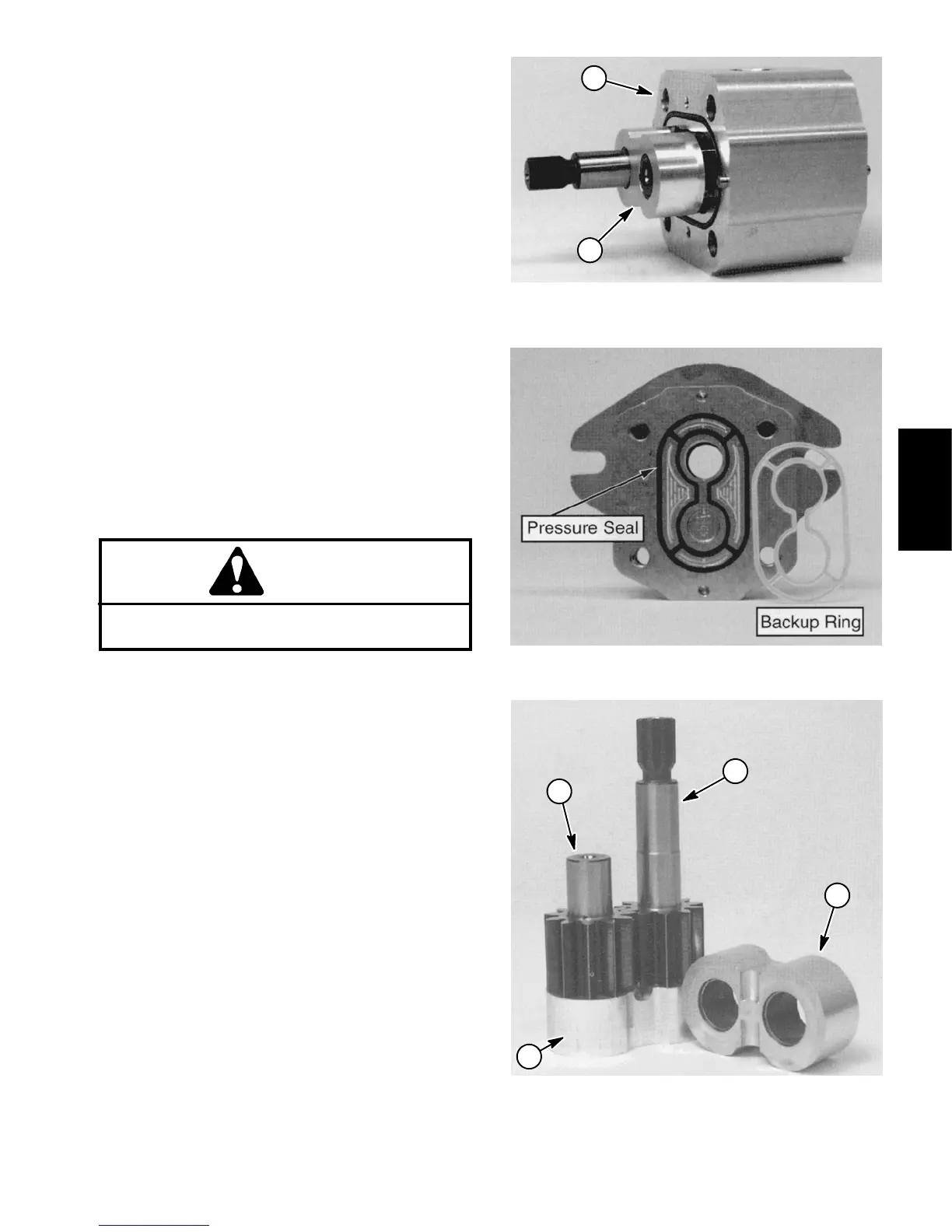
7. Placethemotoronitssideandpushontherearbear-
ingblock to remove the bearingblockandgearset(Fig.
54).
8. Carefully remove and discard O--r ings, pressure
seals and back--up rings (Fig. 55) from motor. Do not
cause any damage to the machined grooves during the
removal process.
IMPORTANT: Make sure not to damage the counter
bore when removing the shaft seal from the front
plate.
9. Positionfrontflangewith sealsideup.Remove shaft
seal.
Inspection
1. Remove any nicks and burrs from all motor compo-
nents with emery cloth.
CAUTION
Use eye protection such as goggles when using
compressed air.
2. Clean all motor components with solvent. Dry all
parts with compressed air.
3. Inspect drive gear, idler gear and bearing blocks
(Fig. 56) for the following:
A. Gear shafts shouldbefree of rough surfacesand
excessivewear at bushing pointsand sealing areas.
Scoring, rough surfaces or wear on gear shafts indi-
cates need for replacement.
B. Gear teeth should be free of excessive scoring
and wear. Any broken or nicked gear teeth must be
replaced.
C. Inspect gear face edge for sharpness. Sharp
edgesof gearswill millintobearingblocksand,thus,
must be replaced.
D. Bearing areas of bearing blocks should not have
excessive wear or scoring.
E. Face of bearing blocks that are in contact with
gears should be f ree of wear, roughness or scoring.
4. Inspect front flange and rear cover for damage or
wear.
1. Motor body 2. Bearing block & gear set
Figure 54
2
1
Figure 55
1. Drive gear
2. Idler gear
3. Bearing block
Figure 56
2
1
3
3
Hydraulic
System

 Loading...


