Greensmaster 3250--D GroomerPage 8 -- 9
3. If equipped, remove rear roller brush from cutting
unit(seeRearRoller BrushRemoval inthe Serviceand
Repairs section of Chapter 7 -- DPA Cutting Units).
4. Remove groomer drive cover (item 2) and groomer
drivebelt( item3)fromgroomerdrive(seeGroomerBelt
Replacement in this section).
5. Loosen cap screws (item 10) that secure front roller
shaft to groomer arms.
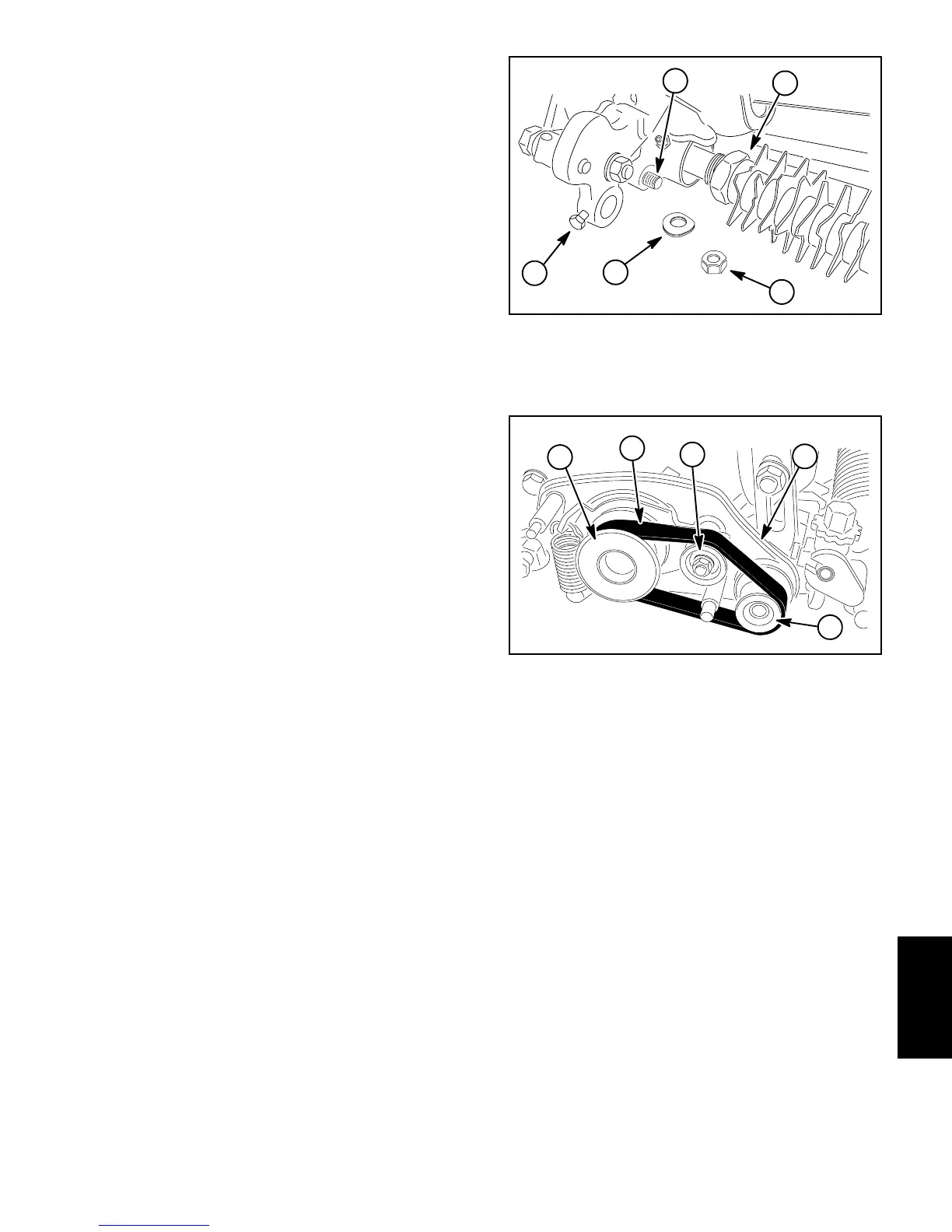
6. Remove lock nut (item 13) and spring washer (item
12)thatsecureRHgroomerarmliftrodtodriveplateas-
sembly (Fig. 5).
7. Remove lock nut (item 21), special washer (item16)
andplowbolt (item22)thatsecure RH groomerarmas-
sembly to drive plate assembly. Do not change height--
of--cut screw adjustment. Remove RH groomer arm
assembly from cutting unit.
8. Remove front roller assembly from cutting unit.
NOTE: To prevent grooming reel shaft from turning
when removing driven pulley, use wrench on shaft flats
to hold shaft.
9. Remove the lock nut (item 1) that secures driven
pulley (item 19) to grooming reel shaft. Remove driven
pulley from shaft.
NOTE: To prevent cutting reel from turning when re-
moving drive pulley, block reel with piece of wood.
10.Loosen and remove drive pulley (item 4) from the
cutting reel shaft.
11.Remove two (2) shoulder bolts (item 5) that secure
the drive plate assembly (item 7) to the cutting unit
frame. Remove the groomer drive plate assembly from
grooming shaft and cutting unit. Locate and retrieve
groomer shim (item 8).
12.Carefullypullthegroomingreelfromthesupportside
plate.
13.Inspect seals, bushings and bearings in drive side
plate,supportplateand groomer arms for wear ordam-
age. Replace components as needed.
Installation (Fig. 4)
1. Apply a light coating of grease to ends of grooming
shaft and also to seal lips in drive side and support
plates. Make sure that all bearings, bushings and seals
are properly installed.
2. Make sure that O--ring (item 27) is installed on
grooming shaft. Apply light coating of grease to O--ring.
1. Roller cap screw
2. Grooming reel assembly
3. Lock nut
4. Spring washer
5. Groomer arm lift rod
Figure 5
4
2
1
3
5
1. Drive pulley
2. Idler pulley
3. Driven pulley
4. Drive plate assembly
5. Groomer drive belt
Figure 6
1
2
4
3
5
3. Carefullyplacegroomingreelassemblyintothesup-
portplatetakingcaretonotdamagesealinsupportplate
orO--ringonshaft.
4. Apply lightcoatingofgrease toO--ring ondriveplate
assembly pivot hub and pilot bore of cutting unit side
plate.
5. Positiongroomershim(item8)todriveplateassem-
bly.
6. Carefully place drive side plate onto groomer shaft
taking care not to damage seals in side plate. Position
side plate to the cutting unit frame and secure with two
shoulderbolts(item5).Makesurethatsideplaterotates
freely after installation.
7. Apply light coating of grease to hub on driven pulley
(item19)taking caretonot getgreaseonbeltsurfaceof
pulley. Slide driven pulley onto the grooming reel shaft
taking care to not damage seal in side plate.
Groomer

 Loading...


