Greensmaster 3250--D Hydraulic SystemPage 4 -- 3 1
Procedure for Charge Relief Valve Pressure
Test
The tractionchargecircuit is designedtoreplacelossof
hydraulic fluid from the closedlooptractioncircuit.The
charge relief valve pressure test will identify if charge
pressure is correct.
1. Make sure hydraulic oil is at normal operating tem-
peraturebyoperatingthemachineforapproximatelyten
(10) minutes.
2. Parkmachineonalevelsurfacewiththecuttingunits
lowered. Make sure engine is off and the parking brake
is engaged. Make sure the hydraulic tank is full.
CAUTION
Before continuing further, read and become fa-
miliar with Precautions for Hydraulic Testing.
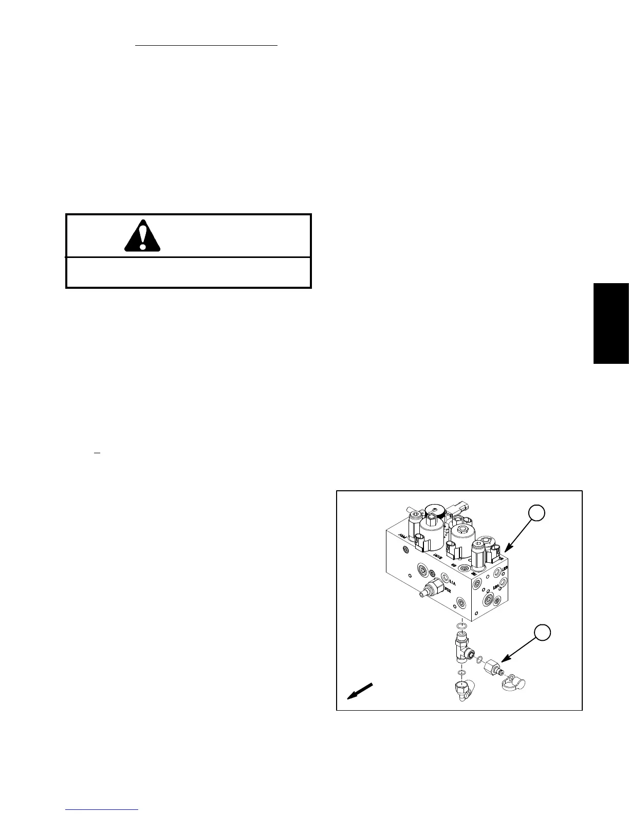
3. Install 1000 PSI (70 bar) pressure gauge with hy-
draulic hose attached to test port in the tee fitting on the
bottom of the control manifold (Fig. 18).
4. Make sure that traction pedal, steering wheel and
joystick are in the neutral position.
5. Start engine and run at low idle speed. Check for hy-
draulic leakage at pressure gauge and correct before
proceeding with test.
6. Move throttle so engine is runningat high idlespeed
(2710 +
50 RPM).
7. Pressure gauge should read approximately 100 to
150PSI(7to10bar).
8. Shut off engine. Record test results.
9. If specification is not met, remove piston pump back
plateassemblythatcontainsthechargereliefvalve(see
Piston (Traction) Pump Service in the Service and Re-
pairs section of this chapter). Repair or replace relief
valve components as necessary.
10.Adynamicchargepressuretestcanbeperformedas
follows:
A. Position machine so that a load can be placed on
thetractionsystem.For example, chainthemachine
to an immovable object or chock all drive wheels to
prevent the machine from moving.
B. Withpressuregaugestillconnected,sitintheop-
eratorseat,startthe engine and movet hrottle so en-
gine is running at high idle speed. Move functional
control lever to the transport position.
C. While monitoring the pressure gauge, push the
tractionpedalintheappropriatedirection(forwardor
reverse) to allow traction system load.
D.Thechargepressureshoulddropnomorethan
20% from no--load charge pressure measured in
step 7 above (e.g. if charge pressure in step 8 is125
PSI (9 bar), charge pressure in forward or reverse
under load should be more than 100 PSI (7 bar)).
E. If charge pressure is good under no load, but
drops below specification when under traction load,
the piston (traction) pump and/or wheel motors
should be suspected of wear and inefficiency. When
thepumpand/ortractionmotor(s)arewornordam-
aged,thechargepumpisnotableto keepupwithin-
ternalleakageintractioncircuitcomponents.Further
testing of the traction circuit should be completed
(see Piston (Traction) Pump Flow and Wheel Motor
Efficiency Tests in this section).
11.Whenchargepressuretesting is complete, discon-
nect pressure gauge from the test port and install dust
cap.
Figure 18
FRONT
1
2
1. Control manifold 2. Test port
Hydraulic
System

 Loading...


