Greensmaster 3250--D Hydraulic SystemPage 4 -- 6 1
Disassembly (Fig. 37)
1. Park machine on a level surface, engage parking
brake,lowercuttingunitsandstopengine.Removekey
from the ignition switch.
2. If necessary, remove mufflertoallowdisassemblyof
traction neutral assembly (Fig. 39). Refer to Exhaust
System in the Service and Repairssection of Chapter3
-- Diesel Engine for additional information on muffler re-
moval.
CAUTION
The extension spring (item 17) is under tension
and may cause personal injury during removal.
Use caution when removing the spring from the
pump neutral assembly.
3. Removecomponentsfromtractionneutralassembly
as needed u sing Figure 37 as a guide.
Assembly (Fig. 37)
1. Install removed components to traction neutral as-
semblyusingFigure37asa guidealongwiththefollow-
ing:
CAUTION
The extension spring (item 17) is under tension
and may cause personal injury during installa-
tion. Use caution when installing the spring to
the pump neutral assembly.
A. If pivot plate (item 32) was removed from pump
trunnion shaft, make sure that both trunnion shaft
and plate bore are thoroughly cleaned before instal-
ling plate to shaft.
B. If damper lever(item4) wasremoved,applyanti-
seize lubricant to bore of mufflermount (item 9) dur-
ing assembly.
C. Make sure that ball bearing (item 16) on neutral
arm (item 11) is properly positioned in pump lever
(item 6) after assembly.
2. Installmufflerifitwasremoved(Fig.39).RefertoEx-
haust System in the Service and Repairs section of
Chapter 3 -- Diesel Engine for additional information on
muffler installation.
3. After traction n eutral assembly has been installed,
make sure that the transmissionisadjustedfortheneu-
tralposition sothatthemachinedoesnotmoveorcreep
when the traction pedal is in neutral.
1. Extension spring
2. Neutral arm
3. Cap screw/flat washer
4. Pup lever
5. Piston pump
6. Upper muffler mount
Figure 38
2
1
3
5
6
4
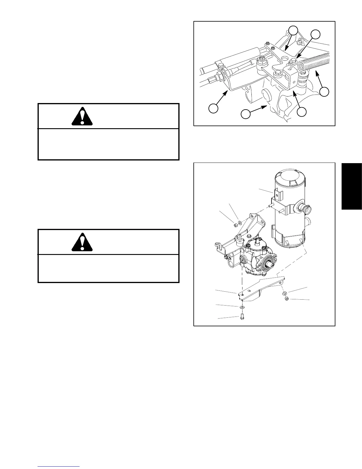
1. Muffler
2. Flat washer (6 used)
3. Lock nut (4 used)
4. Muffler bracket
5. Cap screw (2 used)
Figure 39
2
4
3
5
1
2
2
3
Hydraulic
System

 Loading...


