134
OHA088B
CLEANING AND INSPECTING
1. Clean all A-arm components using a pressure
washer.
2. Clean the ball joint mounting hole of all residual
Loctite, grease, oil, or dirt for installing purposes.
3. Inspect the A-arm for bends, cracks, and worn bushings.
4. Inspect the ball joint mounting holes for cracks or
damage.
5. Inspect the frame mounts for signs of damage, wear,
or weldment damage.
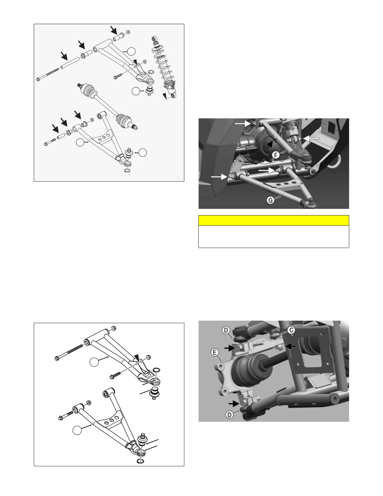
INSTALLING
1. Apply Loctite Primer “T” to the arm socket; then
apply green Loctite 609 to the entire outside diame-
ter of the ball joint (D). Install the ball joint into the
A-arm and secure with the snap ring.
OHA091
2. Install the upper (F) and lower (G) A-arm assemblies
into the frame mounts and secure with the cap
screws. Only finger-tighten at this time.
3. Reattach brake hose clamp to upper A-arm (F).
NOTE: Do not allow the brake caliper to hang from
the cable/hose.
4. Secure the lower eyelet of the shock absorber to the
upper A-arm (F). Tighten nut to 42 ft-lb (56.9 N-m).
5. Secure the A-arm assemblies to the frame mounts
(from step 2). Tighten the cap screws to 42 ft-lb
(56.9 N-m).
OHA088A
6. Install the knuckle assembly (E) onto the ball joints
(D) and secure with cap screws. Tighten to 45 ft-lb
(61 N-m).
7. Install the tie rod end (C) and secure with the nut.
Tighten to 30 ft-lb (40.7 N-m); then install a new cot-
ter pin and spread the pin to secure the nut.
NOTE: During assembly, new cotter pins should be
installed.
OHA087
8. Apply grease to the hub and drive axle splines; then
install the hub assembly onto the drive axle.
CAUTION
Do not tighten the nut beyond the 42 ft-lb (56.9 N-m)
specification. The shock eyelet or mount WILL be dam-
aged.