69
3 If adjustment is needed, use driven clutch shims to
adjust:
0823-704 – 3 mm
0823-705 – 4 mm
0823-706 – 5 mm
0823-752 – 6 mm
0823-753 – 7 mm
OHA153
DRIVE BELT BREAK-IN
A new drive belt requires a break-in period of approxi-
mately 50 miles (80 km).
1. Drive the vehicle approximately 50 miles (80 km) at
3/4 throttle or less. If possible, vary the throttle posi-
tion during the break-in period, not exceeding 3/4
throttle.
2. Do not exceed 40 mph (64 km/h) during the break-in
period.
3. Avoid heavy cargo or towing loads during break-in
period. Use the Low transmission gear if towing.
NOTE: Proper break-in will allow the drive belt to
gain its optimum flexibility and will extend drive belt
life.
Fuel/Lubrication/Cooling
NOTE: It is recommended to use new gaskets, lock
nuts, and seals, and lubricate all internal components
when servicing the engine/transmission.
SPECIAL TOOLS
A number of special tools must be available to the techni-
cian when performing service procedures in this section.
Refer to the current Special Tools Catalog for the appro-
priate tool description.
NOTE: When indicated for use, each special tool
will be identified by its specific name, as shown in the
chart below, and capitalized.
NOTE: Special tools are available from the Service
Department.
TROUBLESHOOTING
1. Verify that the electric fuel pump is operating by lis-
tening for a “whirring” sound for several seconds
after the ignition switch is turned to the ON position.
If no sound can be heard, see Electrical System —
EFI Sensors/Components.
2. Check for a flashing DTC (Diagnostic Trouble Code)
on the LCD gauge. If a code is flashing, see EFI
Diagnostic System in Electrical System section.
3. Make sure there is sufficient clean and fresh regular
87 octane E10 fuel in the gas tank.
Throttle Body
REMOVING
1. Turn the ignition switch to the OFF position; then
remove the ignition switch key.
2. Remove the seat and right-hand side panel; then dis-
connect the battery.
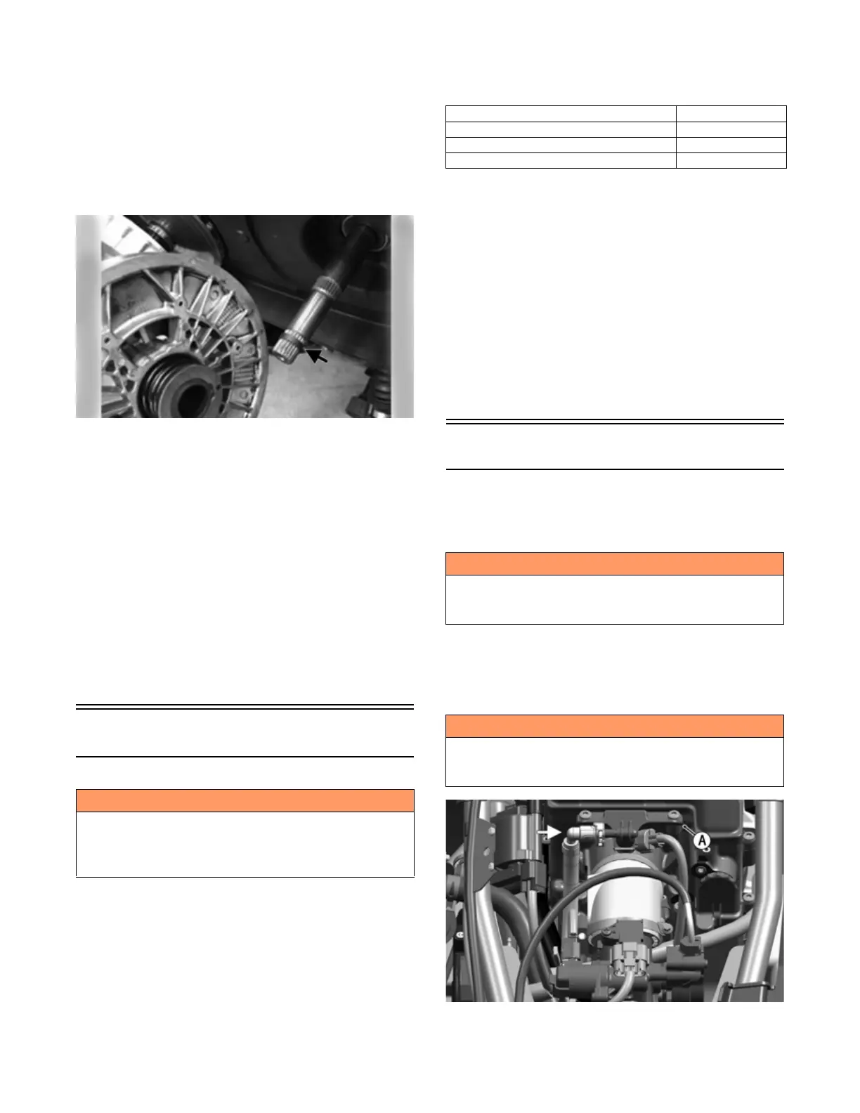
3. Slowly disconnect the gasline hose connector from
the fuel rail (A).
OHA076
4. Remove the screws securing the throttle actuator
cover (B) to the throttle body; then remove the cover.
! WARNING
Whenever any maintenance or inspection is performed
on the fuel system during which there may be fuel leak-
age, there should be no welding, smoking, open flames,
etc., in the area.
Description p/n
Oil Pressure Test Kit
0644-495
Seal Removal Tool
0644-072
Tachometer
Common Tool
! WARNING
Do not turn the ignition switch to the ON position with
the hoses removed. Gasoline will be pumped by the
electric fuel pump causing a safety hazard.
! WARNING
Gasoline may be under pressure. Place an absorbent
towel under the connector to absorb any gasoline spray
when disconnecting.