85
Power Distribution Module
(PDM)
The fuses are located in the Power Distribution Module
on the right side of the ATV behind the access panel.
Remove the seat and the right-hand side panel to access.
If there is any type of electrical system failure, always
check the fuses first.
OHA037
NOTE: The ignition switch must be in the LIGHTS
position.
1. Remove all fuses from the distribution module.
2. Set the meter selector to the DC Voltage position.
3. Connect the black tester lead to ground.
4. Using the red tester lead, contact each end of the fuse
holder connector terminals individually.
5. The meter must show battery voltage from one side
of the connector terminal ends.
NOTE: Battery voltage will be indicated from only
one side of the fuse holder connector terminal; the
other side will show no voltage.
NOTE: When testing the LIGHTS fuse holder, the
headlight switch can be in either position.
NOTE: If the meter shows no battery voltage, trou-
bleshoot the battery, switches, distribution module, or
the main wiring harness.
FUSES
OHA039
1. Set the meter selector to the OHMS position.
2. Connect the red tester lead to one spade end of the
fuse; then connect the black tester lead to the other
spade end.
3. The meter must show less than 1 ohm resistance. If
the meter reads open, replace the fuse.
NOTE: Make sure the fuses are returned to their
proper position according to amperage. Refer to the
fuse block decal for fuse placement.
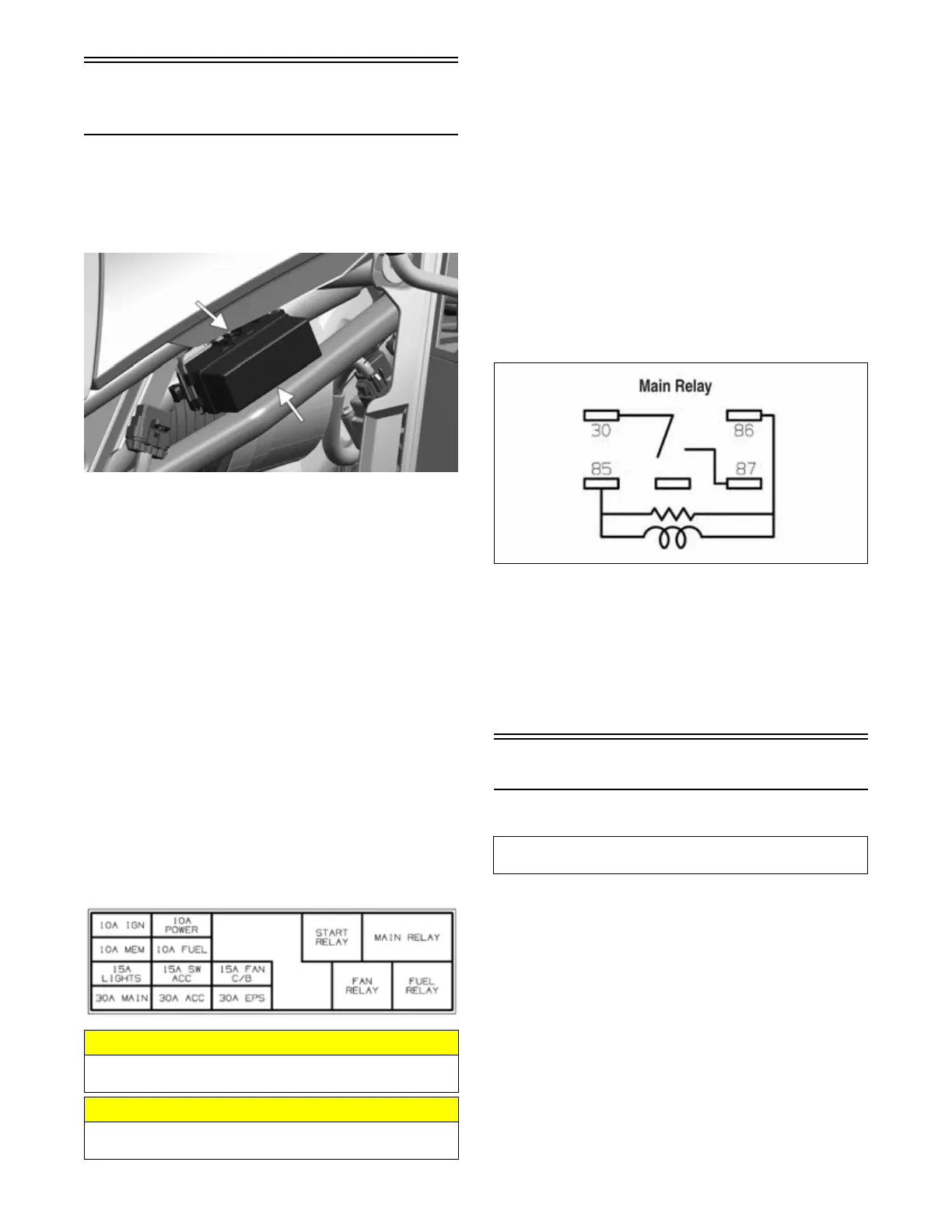
MAIN RELAY
1. Check resistance on pins 85 and 86. The meter
should show 123 ohms ±10%.
2. Check resistance on pins 30 and 87. The meter
should show less than 1 ohm.
XR256
RELAYS
The 4-pin relays are identical plug-in type and can be
checked by switching relay positions. The main relay is
not interchangeable.
NOTE: The module and wiring harness are not a
serviceable components and must be replaced as an
assembly.
EFI Sensors/Components
FUEL INJECTOR
Voltage
Remove the connector from the fuel injector. Place the
red meter lead to the orange wire and black meter lead to
ground. With the ignition switch in the on position the
meter must read battery voltage.
Resistance
With the connector still removed from the injector, place
the red meter lead to either terminal; then connect the black
tester lead to the other terminal. Reading is typically 10.3
ohms ± 10%.
NOTE: If voltage is not present, troubleshoot the
battery, connector pins, wiring harness, fuses, or
relay. If resistance is not present or largely out of
specification, replace the injector.
CAUTION
Always replace a blown fuse with a fuse of the same
type and rating.
CAUTION
Always disconnect the battery when performing resis-
tance tests to avoid damaging the meter.
Component data can be tested using the Dealer Diag-
nostic System. Utilize the Test screen.