22
7. Inspect the handlebar tube for cracks, wear, or
unusual bends.
8. Inspect the handlebar grips for damage or wear.
INSTALLING
1. Place the steering post arm (G) into position on the
frame steering post. Ensure the pressed-in bushing is
secure (see illustration OHA067).
2. Models without EPS Only: Place steering post (E) on
steering post arm (G). Account for bushing (I) and
secure to bracket on frame with clamp and two
M10x1.25 cap screws and flange nuts. Tighten to 42
ft-lb (56.9 N-m) (see illustration OHA066).
3. Install the tie rods and secure with the slotted nuts.
Tighten to 30 ft-lb (40.7 N-m); then install new cot-
ter pins (see illustration OHA067).
NOTE: If the slots do not align with the holes in the
tie rod ends, tighten the nuts just enough to allow
installation of the cotter pins.
NOTE: For models not equipped with electronic
power steering (EPS), proceed to step 8.
4. Position the EPS assembly (F) on the frame bracket
so the lower coupler is engaged in the steering post
arm (G), then install four M10x1.25 cap screws
securing the EPS housing to the frame. Tighten to 35
ft-lb (47.5 N-m) (see illustration OHA065).
5. Connect the 2-pin and 8-pin connectors from the top
of the EPS housing.
6. Install steering post (E) to EPS (F) upper coupler and
secure both upper and lower couplers with M6x1 cap
screws and new lock nuts. Tighten to 11 ft-lb (14.9
N-m) (see illustration OHA064).
7. Install the left shock absorber and tighten to 42 ft-lb
(56.9 N-m).
8. Install front tires.
9. Assemble upper steering post (E) to frame with
lower (B) and upper (C) housing and a cap (D).
Secure with two M8x1.25x45 shoulder screws and
new lock nuts. Tighten to 20 ft-lb (27.1 N-m) (see
illustration OHA063).
10. Install the handlebar and secure with the handlebar
caps. Tighten the screws to 20 ft-lb (27.1 N-m).
11. Install the handlebar cover; then install front body
panels.
Handlebar Grip
REMOVING
1. Using a sharp utility knife, split the handlebar grip
from end to end and peel off the rubber.
2. Using an adhesive solvent, clean all glue residue
from the handlebar.
INSTALLING
1. Apply a liberal amount of Handlebar Grip Adhesive
to the inside of the new grip.
2. Slide the grip onto the handlebar until it is fully
seated with the smooth part of the grip facing up.
NOTE: A quick, firm push is required to seat the
grip completely on the handlebar. Install while the
glue is wet.
3. Wipe off any excess glue.
Throttle Control
REMOVING
1. Remove the two machine screws securing the throt-
tle control to the handlebar.
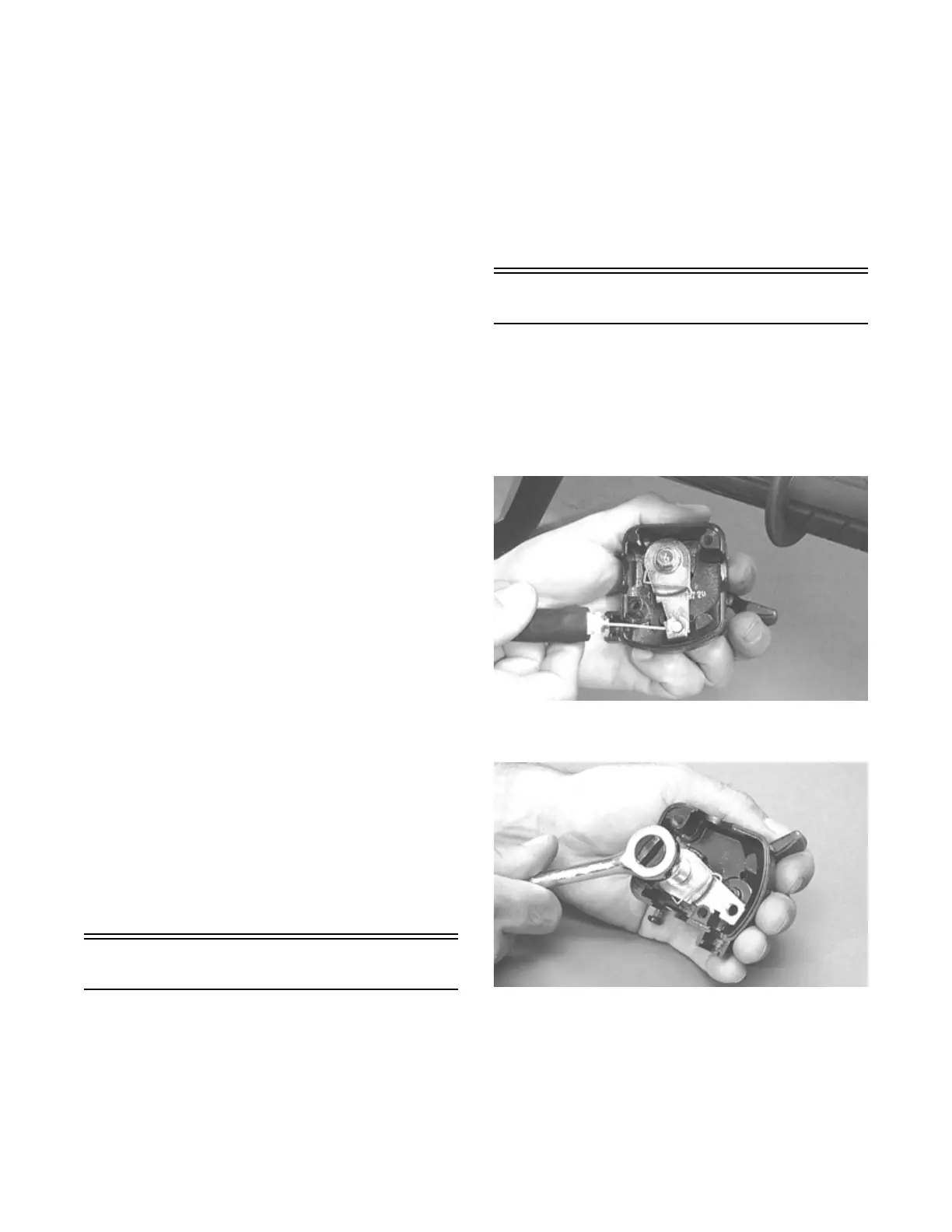
2. Slide the grommet out of the lower half of the throt-
tle control; then remove the cable from the actuator
arm.
AF676E
3. Remove the cap screw, lock washer, and washer
securing the actuator arm to the throttle control lever.
AF677D
4. Remove the actuator arm and account for a bushing.
Note the position of the return spring for installing
purposes.