127
OHA117
OHA116
8. Install clutch, rear duct and clutch covers (see
Engine/Transmission section).
9. Install drive axles (see Drive Axles section), hubs
(see Hub Assembly section) and tires.
10. Remove the vehicle from the support stand.
11. Install exhaust springs and exhaust pipe, right- and
left-hand footwells, rear fender and rack, right- and
left-hand side panels, and seat (see Steer-
ing/Body/Controls section).
Hand Brake Lever/Master
Cylinder Assembly
NOTE: The master cylinder is a non-serviceable
component; it must be replaced as an assembly.
REMOVING
1. Slide a piece of flexible tubing over one of the wheel
bleeder valves and direct the other end into a con-
tainer. Remove the reservoir cover; then open the
bleeder valve. Allow the brake fluid to drain com-
pletely.
NOTE: Compressing the brake lever several times
will quicken the draining process.
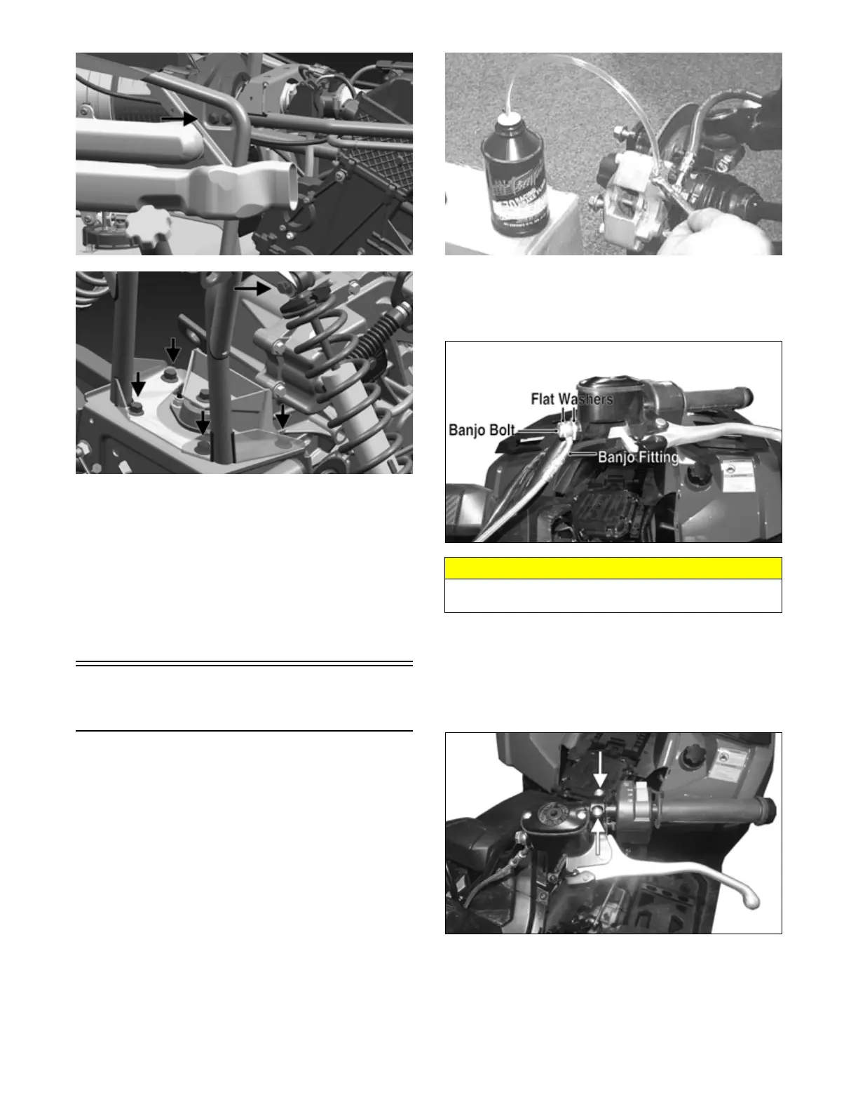
AF637D
2. Place an absorbent towel around the connection to
absorb brake fluid. Remove the banjo-fitting from
the master cylinder. Account for two crush washers
and a banjo-fitting bolt.
XR092A
3. Remove the snap ring and pivot pin securing the
brake lever to the master cylinder housing; then
remove the brake lever and set aside.
4. Remove the clamp screws securing the brake hous-
ing to the handlebar; then remove the assembly from
the handlebar.
XR090A
INSPECTING
1. Inspect the pin securing the brake lever for wear.
2. Inspect the brake lever for elongation of the pivot
hole.
3. Inspect the reservoir for cracks and leakage.
CAUTION
Brake fluid is highly corrosive. Do not spill brake fluid
on any surface of the ATV.