32
Engine/Transmission
This section has been organized into sub-sections which
show a progression of steps for the complete servicing of
the engine and transmission.
To service bottom-side components, the engine must be
removed from the frame. To service top-side or left-side
components, the engine does not have to be removed
from the frame.
NOTE: The manufacturer recommends the use of
new gaskets, lock nuts, and seals and lubricating all
internal components when servicing the engine.
NOTE: A new and an overhauled engine require a
“break-in” period. The first 10 hours (or 200 miles
[320 km]) are most critical to the life of this ATV.
Proper operation during this break-in period will
help ensure maximum life and performance from the
ATV. Instruct the customer to follow the proper
break-in procedure as described in the Operator’s
Manual.
SPECIAL TOOLS
A number of special tools must be available to the techni-
cian when performing service procedures in this section.
Refer to the current Special Tools Catalog for the appro-
priate tool description.
NOTE: When indicated for use, each special tool
will be identified by its specific name, as shown in the
chart below, and capitalized.
NOTE: Special tools are available from the Service
Department.
Removing Engine
1. Remove seat, right- and left-hand side panels, rear
rack and fender, and right- (optional) and left-hand
footwells (see Steering/Body/Controls section).
2. Disconnect the battery (positive cable first).
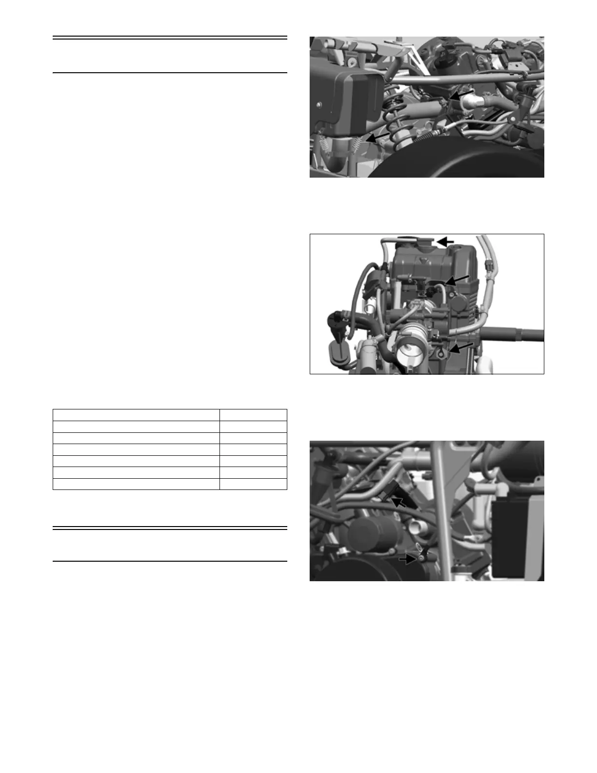
3. Disconnect oxygen (O2) sensor. Remove and discard
two lock nuts holding exhaust pipe to engine, then
unhook muffler springs and remove exhaust pipe.
OHA130
4. Pull spark plug boot from engine, disconnect fuel
injector connection and remove nut securing oil pres-
sure switch eyelet.
OHA139
5. Remove screw holding battery ground wire and
remove ground wire. Replace screw. Disconnect
crankshaft position sensor (CPS) and stator connec-
tors.
OHA140
6. Disconnect coolant temperature sensor connector,
then pull out any push cable ties holding wire har-
ness to upper frame.
Description p/n
Magneto Rotor Remover Set
0444-254
Piston Pin Puller
Common Tool
Spanner Wrench
0444-240
Surface Plate
Common Tool
V Blocks
Common Tool
Clutch Puller
0744-080