135
XR211
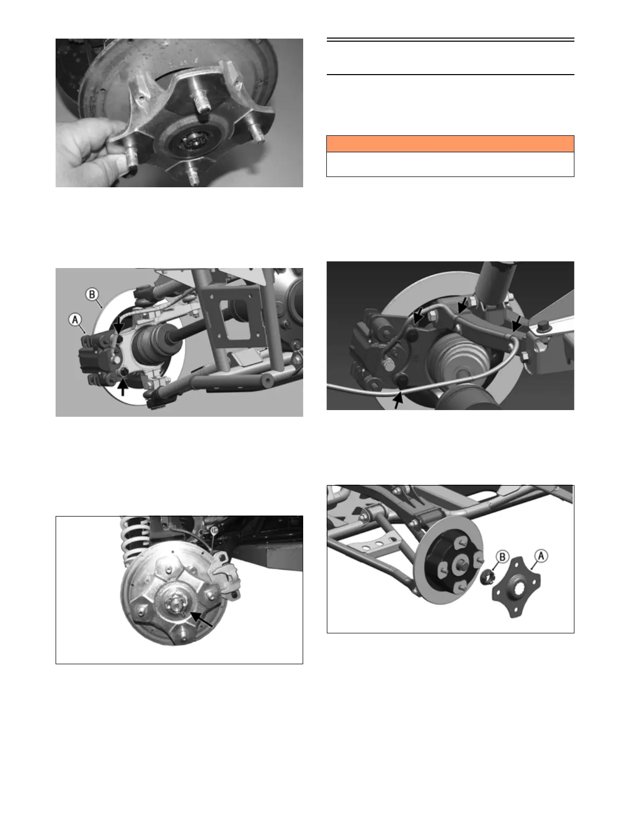
9. Secure the hub assembly (B) to the shaft/axle with
the nut. Tighten only until snug at this point.
10. Secure the brake caliper (A) to the knuckle with two
new “patch-lock” cap screws. Tighten to 20 ft-lb
(27.1 N-m).
OHA086
11. Tighten the hub nut (from step 9) to 200 ft-lb (271
N-m).
NOTE: If the cotter pin does not line up, always
tighten to the next alignment.
12. Install a new cotter pin and spread the pin to secure
the nut.
XR099
13. Install the wheel and tighten the wheel nuts in 20 ft-lb
(27.1 N-m) increments to a final torque of 40 ft-lb
(54.4 N-m) (steel wheel), 60 ft-lb (81.6 N-m) (alumi-
num wheel w/black nuts), or 80 ft-lb (108.8 N-m)
(aluminum wheel w/chrome nuts).
14. Remove the ATV from the support stand.
Rear A-Arms
REMOVING
1. Secure the ATV on a support stand to elevate the
wheels
.
2. Remove the wheel.
3. Remove the clips securing the brakeline hose to the
upper A-arm (right side only).
4. Remove the caliper (right side only). Account for
two cap screws.
OHA092
NOTE: Do not allow the brake caliper to hang from
the cable/hose.
5. Account for bolting plate (A). then remove the hex
nut (B).
OHA093
6. Slide the hub (D) out of the knuckle and set aside.
Account for four screws
! WARNING
Make sure the ATV is solidly supported on the support
stand to avoid injury.