82
RESISTANCE
NOTE: For these tests, the meter selector should be
set to the OHMS position and the primary connector
should be removed from the ignition coil.
Primary Winding
1. Connect the red tester lead to either terminal; then
connect the black tester lead to the other terminal.
2. The meter reading must be within specification.
NOTE: Secondary coil resistance checks are not rec-
ommended. An internal diode in the coil prevents
accurate secondary resistance measurements.
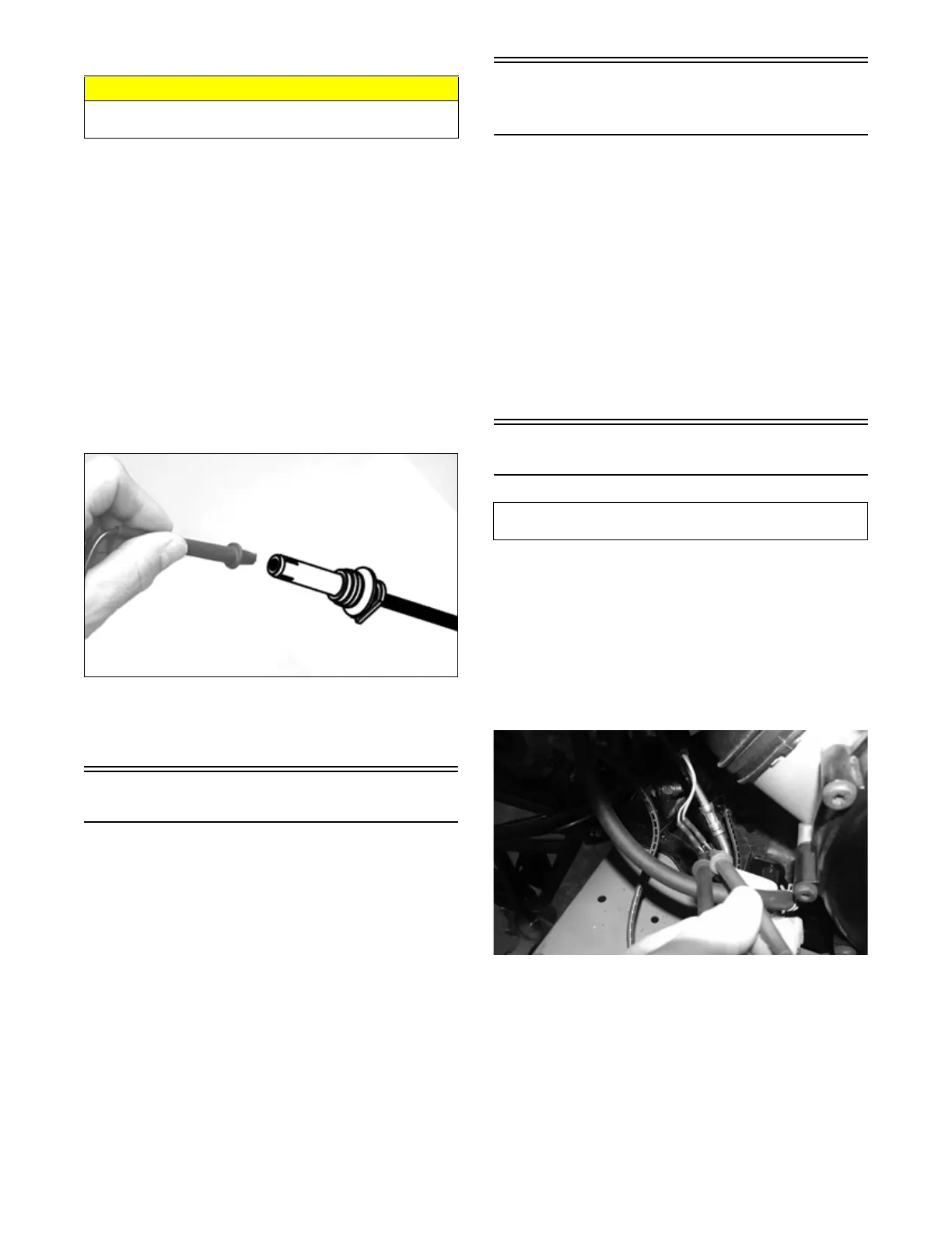
Spark Plug Cap
1. Connect the red tester lead to one end of the cap;
then connect the black tester lead to the other end of
the cap.
OHA099
2. The meter reading must be within specification.
NOTE: If the meter does not read as specified,
replace the spark plug cap.
Ignition Timing
The ignition timing cannot be adjusted; however, verify-
ing ignition timing can aid in troubleshooting other com-
ponents. To verify ignition timing, use the following
procedure:
1. Attach the Timing Light to the spark plug high ten-
sion lead; then remove the timing inspection plug
from the left-side crankcase cover.
2. Using the Tachometer, start the engine and run at
1500 RPM; ignition timing should be 10° BTDC.
3. Install the timing inspection plug.
If ignition timing cannot be verified, the rotor may be
damaged, the key may be sheared, the trigger coil/CKP
sensor bracket may be bent or damaged, or the ECM may
be faulty.
Accessory
Receptacle/Connector
NOTE: This test procedure is for either the recepta-
cle or the connector.
VOLTAGE
1. Turn the ignition switch to the ON position; then set
the meter selector to the DC Voltage position.
2. Connect the red tester lead to the red/white wire or
the orange/black wire; then connect the black tester
lead to ground.
3. The meter must show battery voltage.
NOTE: If the meter shows no battery voltage, trou-
bleshoot the battery, fuse, receptacle, connector, or
the main wiring harness.
Switches
The switch connector is the two-prong connector under
the gas tank on the right side.
NOTE: The ignition switch must be in the ON posi-
tion.
VOLTAGE (Brake Light)
1. Set the meter selector to the DC Voltage position.
2. Connect the red tester to the orange wire; then con-
nect the black tester lead to the red/blue wire.
XR109
3. The meter must show battery voltage.
NOTE: If the meter shows no battery voltage, trou-
bleshoot the battery, fuses, switch, relay, or the main
wiring harness.
NOTE: If the meter shows battery voltage, the main
wiring harness is good; proceed to test the
switch/component, the connector, and the switch wir-
ing harness for resistance.
CAUTION
Always disconnect the battery when performing resis-
tance tests to avoid damaging the meter.
Component data can be retrieved using the Dealer
Diagnostic System. Utilize the Sensor Data screen.