83
RESISTANCE (Brake Light)
1. Set the meter selector to the OHMS position.
2. Connect the red tester lead to one black wire; then
connect the black tester lead to the other black wire.
3. When the brake pedal is depressed, the meter must
show less than 1 ohm.
NOTE: If the meter shows more than 1 ohm of resis-
tance, replace the switch.
RESISTANCE (High Beam)
The connector is the double connector next to the steer-
ing post. To access the connector, the side panels and
console must be removed (see Steering/Body/Controls).
NOTE: These tests should be made on the switch
side of the connector.
1. Set the meter selector to the OHMS position.
2. Connect the red tester lead to the brown/black wire
for models with accent lights and the gray wire for
models without accent lights; then connect the black
tester lead to the blue wire for models with accent
lights and the yellow wire for models without accent
lights.
3. With the dimmer switch in the HI position, the meter
must show less than 1 ohm.
NOTE: If the meter shows more than 1 ohm of resis-
tance, replace the switch.
RESISTANCE (Low Beam)
1. Connect the red tester lead to the brown/black wire
for models with accent lights and the gray wire for
models without accent lights; then connect the black
tester lead to the white wire for both.
2. With the dimmer switch in the LO position, the
meter must show an open circuit.
NOTE: If the meter reads resistance, replace the
switch.
DIODE (Starter Button)
1. Disconnect the 4-pin connector on the switch side of
the connector plate.
2. Connect the red tester lead to the red/ yellow wire
and the black tester lead to the black/white wire.
3. With the starter button depressed, the reading should
be less than 1 ohm.
NOTE: If the meter does not show as specified,
replace the left-side control assembly.
RESISTANCE (Engine Stop)
1. Set the meter selector to the OHMS position.
2. Connect the red tester lead to the brown/blue wire;
then connect the black tester lead to the black/white
wire.
3. With the switch in the OFF position, the meter must
show an open circuit.
4. With the switch in the RUN position, the meter must
show less than 1 ohm.
NOTE: If the meter shows more than 1 ohm of resis-
tance, replace the left-side control assembly.
RESISTANCE (Reverse Override)
The connector is the four-prong white one next to the
steering post. To access the connector, the front rack and
front fenders must be removed (see Steering/Body/Con-
trols).
1. Set the meter selector to the OHMS position.
2. Connect the tester leads as shown:
3. Depress and hold the reverse override button. The
meter must show less than 1 ohm.
NOTE: If the meter does not show as specified,
replace the switch.
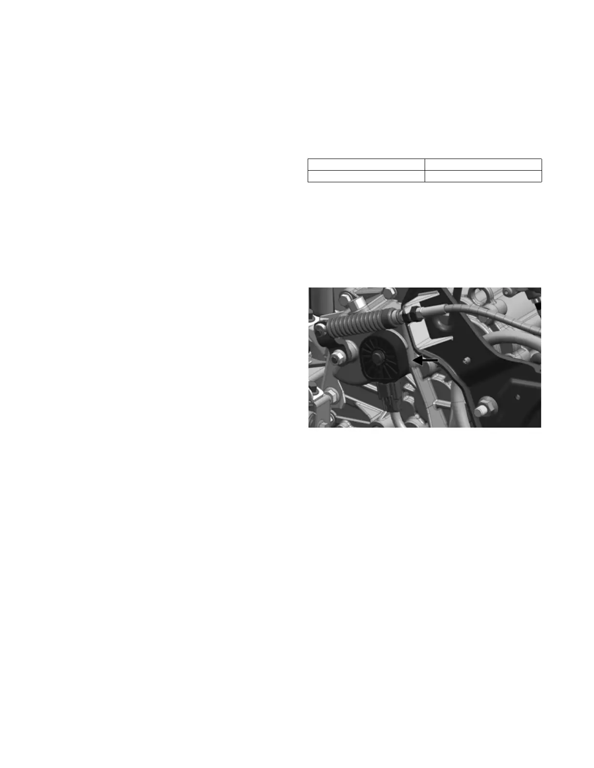
RESISTANCE (Gear Position)
The gear position switch is located on the transaxle
behind the shift arm.
OHA100
1. Disconnect the gear position switch connector; then
using a meter, test the switch in each position as fol-
lows. Resistance must be less than 1 ohm for all
tests.
Red Tester Lead Black Tester Lead
Blue/Red Green/Red