84
ATV-3083
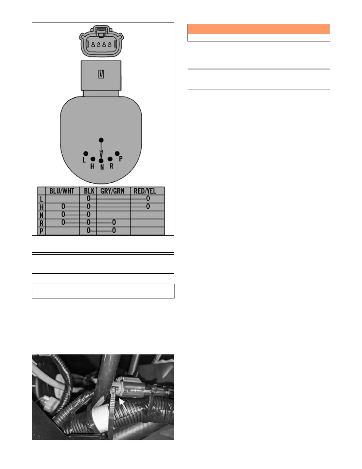
2. Connect the harness to the gear position switch.
Fan Motor
1. Remove front fender to access fan connector.
Remove cable ties if necessary.
NOTE: To determine if the fan motor is good, con-
nect the blue wire from the fan connector to the posi-
tive side of a 12-volt battery; then connect the black
wire from the fan connector to the negative side. The
fan should operate.
OHA104
NOTE: Fan motor resistance checks are not recom-
mended. Resistance values change with the motor
commutator position.
Lights
VOLTAGE (Headlights)
NOTE: Perform these tests on the main harness side
of all four connectors. Also, the ignition switch must
be in the LIGHTS position.
1. Set the meter selector to the DC Voltage position.
2. Connect the red tester lead to the white wire; then
connect the black tester lead to the black wire.
3. With the headlight switch in the Low position, the
meter must show battery voltage.
4. Move the red tester lead to the yellow wire. With the
dimmer switch in the High position, the meter must
show battery voltage.
5. On models with an LED lightbar, connect the red tester
lead to the gray wire and the black tester lead to the
black wire. The meter must show battery voltage.
NOTE: If battery voltage is not shown in any test,
inspect the LIGHTS fuse, battery, main wiring har-
ness, connectors, or the left handlebar switch.
VOLTAGE (Taillight)
NOTE: Perform this test on the main harness side of
the connector. Also, the ignition switch should be in
the LIGHTS position.
1. Set the meter selector to the DC Voltage position.
2. Connect the red tester lead to the gray wire; then
connect the black tester lead to the black wire.
3. With the ignition key in the LIGHTS position, the
meter must show battery voltage.
NOTE: If the meter shows no voltage, inspect fuses,
wiring harness, connectors, and switches.
VOLTAGE (Brake Light)
NOTE: Perform this test on the main harness side of
the connector. Also, the ignition switch should be in
the ON position and the brake (either foot pedal or
hand lever) must be applied.
1. Set the meter selector to the DC Voltage position.
2. Connect the red tester lead to the red/blue wire; then
connect the black tester lead to the black wire.
3. With either brake applied, the meter must show bat-
tery voltage.
NOTE: If the meter shows no voltage, inspect fuses,
wiring harness, connectors, and switches.
This component can be tested using the Dealer Diag-
nostic System. Utilize the Test screen.
! WARNING
Care should be taken to keep clear of the fan blades.