81
Ignition Switch
The ignition switch harness connects to the switch with a
four-pin connector. To access the connector, remove the
ignition switch nut. Switch will drop under front fender.
Access switch and harness, and press the connector
release tab. Pull the connector from the switch.
NOTE: Ignition switch and switch harness can be
accessed on the left-hand side under front fender.
OHA098
OHA097
VOLTAGE
NOTE: Perform this test on the harness connector.
1. Set the meter selector to the DC Voltage position.
2. Connect the red meter lead to either red wire; then
connect the black meter lead to ground.
3. Meter must show battery voltage.
NOTE: If the meter shows no battery voltage, trou-
bleshoot the battery or the main wiring harness.
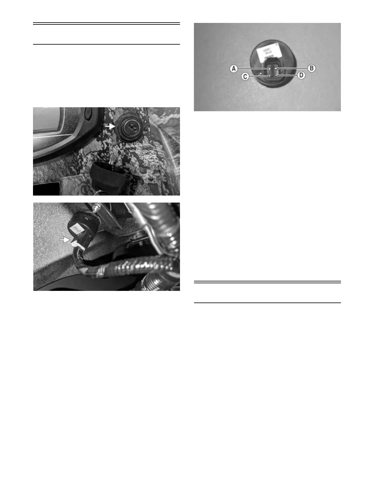
RESISTANCE
NOTE: Perform this test on the switch using the fol-
lowing procedure:
CF274A
1. Turn the ignition switch to the ON position.
2. Set the meter selector to the OHMS position.
3. Connect either tester lead to pin C; then connect the
other tester lead to pin D.
4. The meter must show less than 1 ohm.
5. Turn the ignition switch to the LIGHTS position.
6. Connect either tester lead to pin A; then connect the
other tester lead to pin B.
7. The meter must show less than 1 ohm.
8. Connect either tester lead to pin C; then connect the
other tester lead to pin D.
9. The meter must show less than 1 ohm.
10. With the switch in the OFF position, connect the red
tester lead and the black tester lead to each of the
remaining pins. The meter must show an open circuit
on all pins.
NOTE: If the meter shows more than 1 ohm of resis-
tance, replace the switch.
Ignition Coil
The ignition coil is on the frame above the engine. To
access the coil, the right side panel must be removed.
VOLTAGE
Primary Coil
1. Set the meter selector to the DC Voltage position;
then disconnect the two wires from the coil.
2. Connect the red tester lead to the orange wire and the
black tester lead to the white/blue wire.
3. Turn the ignition switch to the ON position. The
meter must show battery voltage.
Secondary Coil
1. Connect the primary ignition coil connector. Remove
the spark plug cap from the spark plug.
2. Connect the spark plug cap to Ignition Test Plug or
other suitable tool; then ground the tool away from
the spark plug hole. While turning the engine over,
check for sufficient spark.