65
4. Using the Drive Clutch Retention Tool (resting on the
driven clutch) to hold the drive clutch, tighten the cap
screw and washer securing the cap screw to the
crankshaft. Tighten to 51 ft-lb (69 N-m).
VTA085
5. Install the drive belt.
6. With the drive belt properly positioned in the drive
clutch and driven clutch, turn the belt tool counter-
clockwise and roll the belt back and forth to allow
the driven clutch sheaves to fully close.
7. Install the CVT cover and secure with the cap
screws. Tighten the cap screws in sequence shown in
illustration OHA047A to 24 in-lb (2.7 N-m).
OHA047A
8. Install left-hand footwell, left-hand side panel and
seat (see Steering/Body/Controls section).
Servicing Clutch
Components
NOTE: The engine does not have to be removed
from the frame for this procedure.
SPECIAL TOOLS
A number of special tools must be available to the techni-
cian when performing service procedures in this section.
Refer to the current Special Tools Catalog for the appro-
priate tool description.
NOTE: When indicated for use, each special tool
will be identified by its specific name, as shown in the
chart below, and capitalized.
NOTE: Special tools are available from the Service
Department.
DRIVE CLUTCH
Disassembling
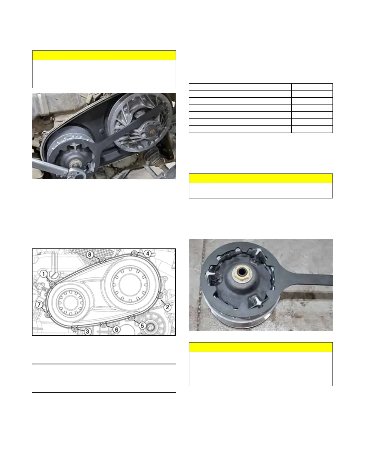
1. Using the Drive Clutch Retention Tool to hold the
drive clutch, carefully loosen the clutch cover nut.
Once the nut is loose remove the tool; then apply
pressure to the cover plate and continue to remove
the nut and washer. Discard the nut.
VTA-087.
2. Remove the spring. Account for two washers and the
spring cup.
CAUTION
When installing the drive clutch, do not tighten the cap
screw with any kind of impact tool. Tighten cap screw
using a hand torque wrench only. Failure to do so could
result in stationary sheave damage.
Description p/n
Belt Removal Tool (provided in tool kit)
0744-098
Drive Clutch Puller
0644-650
Drive Clutch Spanner Wrench
0644-136
Driven Clutch Compressor Tool
Common Tool
Clutch Retention Tool — XX
0444-652
Clutch Alignment Bar
0644-651
CAUTION
Use caution when removing the nut holding the
clutch cover as it is under spring pressure.
CAUTION
If the movable sheave does not have spring pressure
when starting to loosen the clutch compressor, the
spring cup may be seized in the movable sheave. Rein-
stall the nut and replace the clutch assembly to prevent
personal injury.