103
MOD517
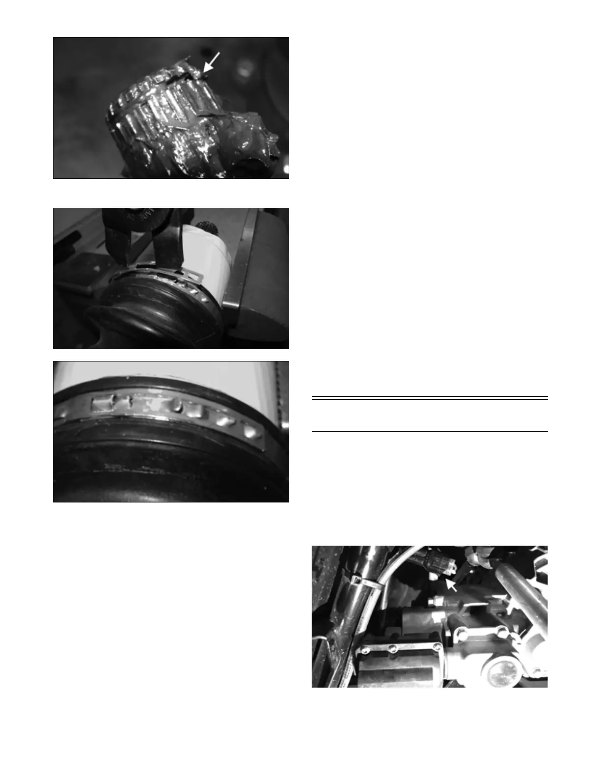
5. Install the large diameter boot clamp
.
MOD514
MOD518
NOTE: Steps 1-5 can be used to replace the out-
board boot.
NOTE: In the outboard boot, use the final 55 grams
(1/3 of contents) of grease from the pack in the bear-
ing housing.
INSTALLING REAR DRIVE AXLE
NOTE: It is recommended to apply grease on the
splines for the rear drive axles going into the tran-
saxle. Prior to installing verify the location of the
O-ring for the rear drive axles.
1. Slide the drive axle into place in the gear case.
NOTE: To ensure proper seating of the axle, give it a
light pull; the axle should remain “clipped” in place.
2. Swing the knuckle up and onto the drive axle; then
place the knuckle into place in the upper A-arm.
Secure the knuckle to the A-arm with cap screws and
new lock nuts. Tighten to 45 ft-lb (61.2 N-m).
3. Install the hubs (see Hub Assembly in this section).
4.
Install the wheel; then using a crisscross pattern, tighten
the wheel nuts
in 20 ft-lb (27.2 N-m) increments to a
final torque of 40 ft-lb (54.4 N-m) (steel wheel), 60
ft-lb (81.6 N-m) (aluminum wheel w/black nuts), or
80 ft-lb (108.8 N-m) (aluminum wheel w/chrome
nuts)
.
5. Remove the vehicle from the support stand and
release the parking brake.
INSTALLING FRONT DRIVE AXLE
1. Position the drive axle in the gear case and steering
knuckle.
NOTE: To ensure proper axle seating, give it a light
pull; the axle should remain “clipped” in place.
2. Insert the ball joints into the steering knuckles and
secure with new cap screws and new lock nuts tight-
ened to 45 ft-lb (61.2 N-m); then install the tie rods
to the steering knuckles and tighten to 30 ft-lb (40.8
N-m).
3. Install the hubs (see Hub Assembly in this section).
4.
Install the wheel; then using a crisscross pattern, tighten
the wheel nuts
in 20 ft-lb (27.2 N-m) increments to a
final torque of 40 ft-lb (54.4 N-m) (steel wheel), 60
ft-lb (81.6 N-m) (aluminum wheel w/black nuts), or
80 ft-lb (108.8 N-m) (aluminum wheel w/chrome
nuts).
5. Check the front differential oil level and add oil as
necessary.
Front Drive Actuator
NOTE: The actuator is only serviceable as an
assembly.
NOTE: The actuator will operate only when the
ignition switch is in the ON position.
REMOVING
1. Disconnect actuator electrical plug from wiring har-
ness.
OHA162
2. Using an 8 mm socket or wrench, remove the actua-
tor guard two side fasteners and use a 12 mm socket
to remove one rear fastener. Remove guard.