71
Gas Tank
REMOVING
1. Remove the seat, right- and left-hand side panels,
and left-hand footwell.
NOTE: Removing the CVT intake/inlet duct makes
it easier to remove the gas tank.
2. Remove battery bracket, and disconnect (negative
cable first) and remove battery.
3. Remove cable tie holding coolant hose to gas tank
bracket.
4. Remove the cap screw holding the starter relay sole-
noid and the two cap screws holding the winch sole-
noid (if equipped) to the tank bracket and move both
solenoids aside. Remove cap screw holding tank
bracket to the frame and remove bracket.
OHA078
5. Disconnect the fuel pump connector (A) and gasline
hose (B) from the fuel pump. Remove the vent hose
(C) and cap the vent fitting.
OHA079
6. Remove the cable ties securing the vent hose to the
frame.
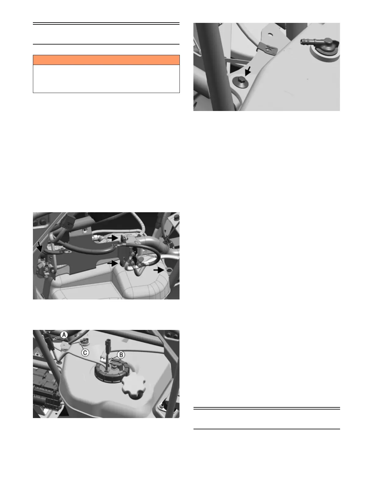
7. Remove the screw and lock nut securing the gas tank
mounting tab to the frame. Slide gas tank out from
left side.
OHA080
CLEANING AND INSPECTING
1. Clean all gas tank components with parts-cleaning
solvent.
2. Inspect all hoses for cracks or leaks.
3. Inspect tank cap and tank for leaks, holes, and dam-
aged threads.
4. Remove the fuel level sensor/fuel pick-up assembly
and inspect the fuel level sensor and fuel screen.
NOTE: If the fuel level sensor has failed or may be
faulty, see Electrical System — EFI Sensors/Compo-
nents.
INSTALLING
1. Slide the gas tank into the vehicle from the left side.
2. Secure gas tank mounting tab to the frame with
screw and new lock nut. Tighten nut to 8 ft-lb (10.8
N-m).
NOTE: Ensure the tab of the mounting bracket is in
place on the gas tank.
3. Install vent hose after uncapping the fitting. Secure
the vent hose to the frame with cable ties (as noted
during removing), then connect the gasline hose and
fuel pump connector.
4. Install tank bracket and secure to frame with cap
screw. Tighten to 8 ft-lb (10.8 N-m). Then install
starter relay solenoid and secure with cap screw and
nut with washer. Tighten to 8 ft-lb (10.8 N-m). Install
winch solenoid (if equipped) and secure with two
cap screws and nuts with washers. Tighten to 6 ft-lb
(8.1 N-m).
5. If required, reattach purge valve to tank bracket
hook.
6. Install the battery and connect the battery cables
(positive cable first); then install the battery bracket.
7. Install the fenders; then install the side panels and
seat.
Oil Pump
TESTING OIL PUMP PRESSURE
NOTE: The engine must be warmed up to the speci-
fied temperature for this test.
! WARNING
Whenever any maintenance or inspection is made on
the fuel system during which there may be fuel leakage,
there should be no welding, smoking, open flames, etc.,
in the area.