49
LYC046
Oil Pan/Pickup/Pump/Pressure Valve
1. Remove O-Ring from oil pressure pump; then grease
and reinstall new O-ring.
2. Inspect and clean upper and lower oil pan.
3. Inspect plug, oil level stick and oil pressure pump
parts. Account for O-rings and key.
4. Oil pressure valve is located in lower crankcase.
Remove one screw holding clamp and remove and
inspect pressure valve, guide, and spring. Check for
ease of movement. Replace parts if damaged.
5. Reinstall valve, guide, and spring. Secure with clamp
and one screw. Tighten to 16 ft-lb (22 N-m)
LYC049
Assembling Engine
NOTE: The manufacturer recommends that new
gaskets, seals, and O-rings be installed whenever
assembling the engine.
NOTE: For assembly purposes, use oil-dissolvable
molybdenum disulfide grease as engine-assembly
grease.
NOTE: Refer to the Assembly Schematic at the end
of this section for visual checks and to verify parts.
1. Install four new studs in upper crankcase so the bolt
protrusion is 178 mm ± 2 mm. Tighten to 15 ft-lb ±
1.5 ft-lb (20 N-m ± 2 N-m).
2. Visually check that all fittings, sleeves and plugs are
in place and accounted for in the crankcase halves
(see Assembly Schematic at the end of this section).
3. The water pump can be assembled to the upper
crankcase at this time. Do not install the hose at this
time (see Fuel/Lubrication/Cooling section).
LYC046
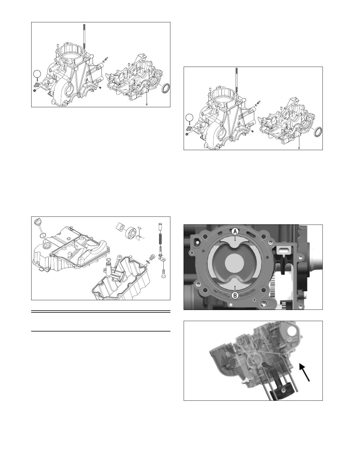
4. Verify cylinder sleeve is installed in upper crankcase
(see Servicing Engine Components — Cylinder
Sleeve). Oil piston assembly ring. Insert conrod and
piston assembly down through top of cylinder
sleeve. Orient piston top as noted when disassem-
bled. The arrow or exhaust lobe (A) should point to
starter side.
NOTE: An arrow marks the exhaust side on new
pistons and may be visible if area is clean.
LYC021
L
LYC020A