48
CONNECTING ROD (CONROD)
1. Check small end for wear and discoloration.
Measuring Small End
1. Insert a snap gauge into the upper conrod small end
bore; then remove the gauge and measure it with a
micrometer.
2. Maximum diameter must not exceed specifications.
3. Zero the indicator and push the small end of the con-
rod away from the dial indicator.
4. Maximum deflection must not exceed specifications.
Measuring Big End/Conrod Bearings
1. Conrod big end must be measured when assembled.
2. Install bearing centered and with parting edges of
conrod halves even with bearing edges.
3. Assemble the cap end, oil bolt heads and threads, and
secure cap end to conrod. Tighten bolts in three alter-
nating steps: 88 in-lb (10 N-m); then 15 ft-lb (20
N-m); and finally a 60° turn.
NOTE: Bearing clearance may be confirmed using
an indicator strip such as PLASTIGAUGE
®
.
LYC023
BALANCER SHAFT
Inspecting
1. Inspect for wear on teeth.
2. Inspect balancer journal surface.
3. Replace if worn or damaged.
LYC0025
PISTON
Assembling
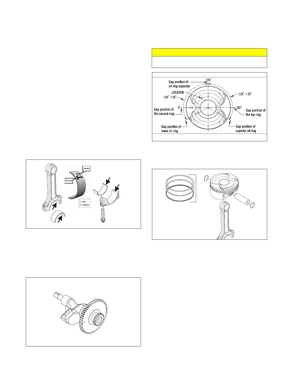
1. Install rings on piston per gap specifications. Orien-
tate gaps as shown.
0754-342
2. Assemble piston and conrod and insert pin in previ-
ously marked direction. Secure with circlips, making
sure they are properly seated.
LYC024
CRANKCASE
Cleaning/Inspecting
1. Wash upper and lower parts with parts cleaner,
2. Visually check stud bolt threads at housing and
remove debris.
3. Check that all fittings, sleeves and plugs are in place
and accounted for.
4. If oil pressure switch (A) needs to be removed or
replaced, reinstall using Loctite 542.
CAUTION
Incorrect installation of the piston rings will result in
engine damage.