50
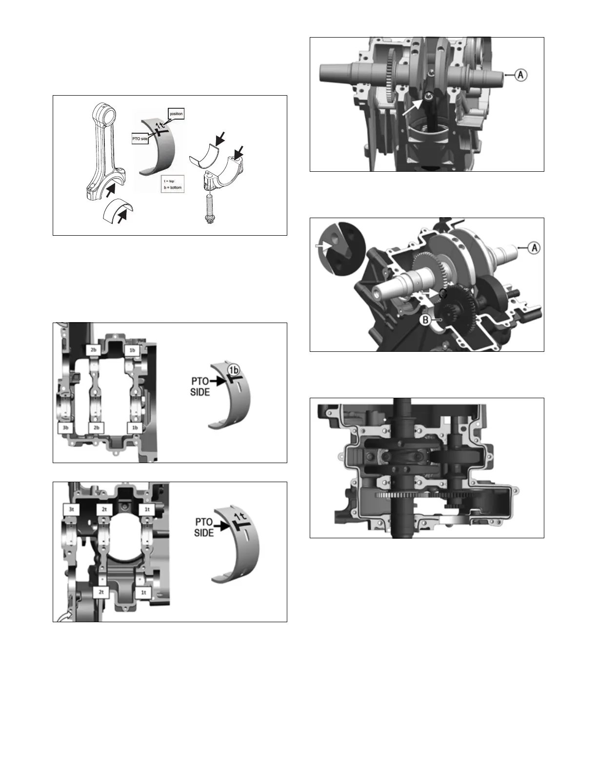
5. Clean bearing surfaces, and install conrod and con-
rod endcap bearings centered and with parting edges
of conrod halves even with bearing edges. See Ser-
vicing Engine Components — Connecting Rod
(Conrod) for bearing selection.
LYC023
6. Clean out bearing supports on crankcase halves and
install bearing halves as noted in disassembly. Place
bearings into locating notches on crankcase halves
and align bearing half edges with crankcase parting
line edges. Oil the bearings. See Servicing Engine
Components — Crankshaft for bearing selection.
LYC060
LYC061
NOTE: Prior to crankshaft and balance shaft
assembly, apply a small amount of oil on shaft bearing
journals.
7. Install crankshaft (A) to fit with conrod. Install con-
rod end cap. Secure with two new screws. Oil bolt
heads and threads, and tighten in alternating steps:
88 in-lb (10 N-m); then 15 ft-lb (20 N-m); and finally
a 60° turn.
LYC047
8. Insert balancer shaft (B) and align sprocket marks to
crankshaft sprocket mark.
LYC064
9. Apply a thin line of liquid seal to sealing surface of
upper crankcase as indicated in illustration LYC063.
LYC063
10. Install bottom half of crankcase (A). Position using
locating pins and bearing of balancer shaft.
NOTE: Upper and lower crankcase pieces are ser-
viced as an assembly.