51
LYC015
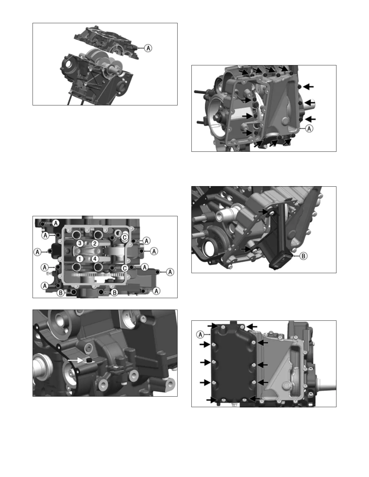
11. Secure lower crankcase to upper crankcase with 11 (one
on top) M6x35 screws (A), two M6x90 screws (B) and
two M8x40 screws (C), noting the correct location in
illustration LYC014 below. Only pre-tighten these fas-
teners. Then on the four center M8 flange bolts, lubri-
cate the threads and flange heads with mounting grease
and install in a crisscross pattern.
12. Tighten the four M8 flange bolts in a crisscross pat-
tern in steps: 88 in-lb (10 N-m); then 22 ft-lb (30
N-m): and finally a 70° turn.
13. Tighten the two M8x40 screws (C) to 17.7 ft-lb (24 N-m).
14. Tighten the two M6x90 screws (B) and 11 M6x35
screws (A) to 88 in-lb (10 N-m).
LYC014
LYC037
15. Confirm the oil pressure regulator valve is installed
on the lower crankcase (see Servicing Engine Com-
ponents — Oil Pan/Pickup/Pump/Pressure Valve
section).
16. Clean sealant surface on bottom of lower crankcase
and the upper oil pan. Apply liquid seal and two
locating pins to crankcase bottom and position top
oil pan (A) on crankcase. Secure with 13 top pan
screws: three on inside and 10 on outer edges.
Tighten to 88 in-lb (10 N-m).
OHA009
17. Install oil pickup assembly (B), account for O-ring
and secure with two screws. Tighten to 88 in-lb (10
N-m).
OHA011
18. Clean sealing surface on upper oil pan and lower oil
pan. Apply liquid seal and place two locating pins
onto upper oil pan. Position lower oil pan (A) and
secure to upper pan with 10 screws. Tighten to 88
in-lb (10 N-m).
LYC010
19. Check that the oil drain with seal ring and oil dip
stick with O-ring are installed (see Servicing Engine
Components section or refer to Assembly Sche-
matic).