52
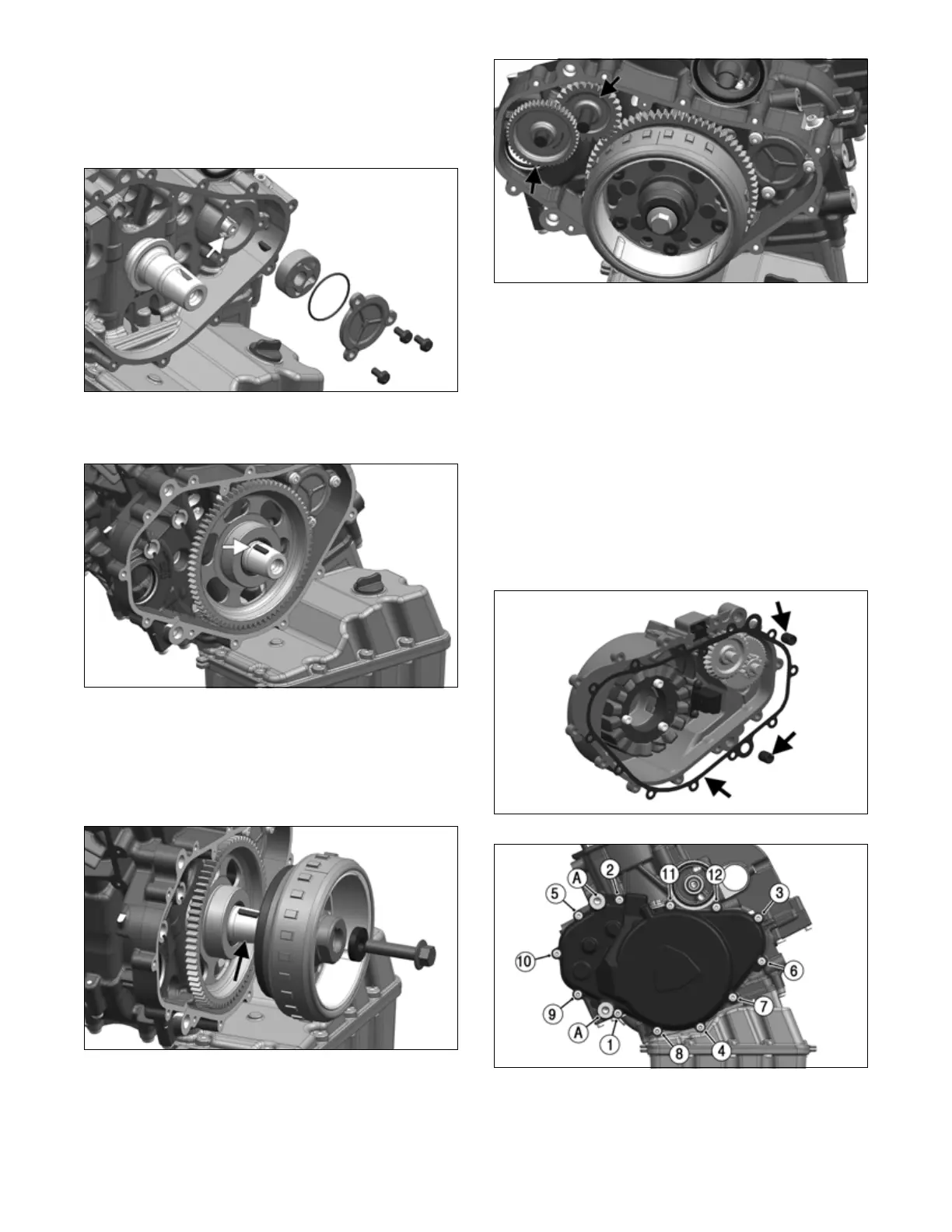
20. Wipe out any residual liquid seal in bore for oil pres-
sure pump. Insert key in balancer shaft and then
insert oil pressure pump. Install new O-ring on oil
pressure pump cover. Secure oil pressure pump cover
to crankcase with 3 screws. Tighten to 45 in-lb (5
N-m).
LYC013
21. Oil and install ring gear on crankshaft. Insert mag-
neto key in crankshaft.
LYC051
22. Clean outer taper on crankshaft and inner taper on
rotor with alcohol and slide rotor assembly on shaft
aligning with key. Install washer and bolt. Tighten to
88 ft-lb (120 N-m). Verify free rotation of large
starter gear in the counterclockwise direction. The
gear should lock up in the clockwise direction.
LYC052
23. Oil and install starter gear shafts and then install the
two starter gears on the crankcase in the direction
noted when during disassembly.
LYC053
24. Position locating pins on crankcase. Make sure seal-
ing surface of generator cover and crankcase are free
of dirt and residual sealant. Use locating pins to posi-
tion new gasket on crankcase. Then install cover
using locating pins, making sure to squarely align the
cover to crankcase. Remove locating pins.
25. Install a 3.5 mm washer and a M10 bolt into each of
the two engine-to-transaxle plate mounting holes
(A). Tighten M10 bolts to 35 ft-lb (47.5 N-m).
Secure cover to the crankcase with 12 screws.
Tighten to 88 in-lb (10 N-m) in the sequence shown.
Remove M10 bolts and washers.
26. Visually check that the plug and insert are installed
on cover (see Assembly Schematic at end of this sec-
tion).
LYC008B
LYC008A
27. Make sure threaded sleeve is pushed into the bore of
chain tensioner guide rail (see Servicing Engine
Components section).