53
28. Insert chain tensioner guide rail into chain case.
Secure with ring seal and screw. Tighten to 80 in-lb
(9 N-m).
LYC054
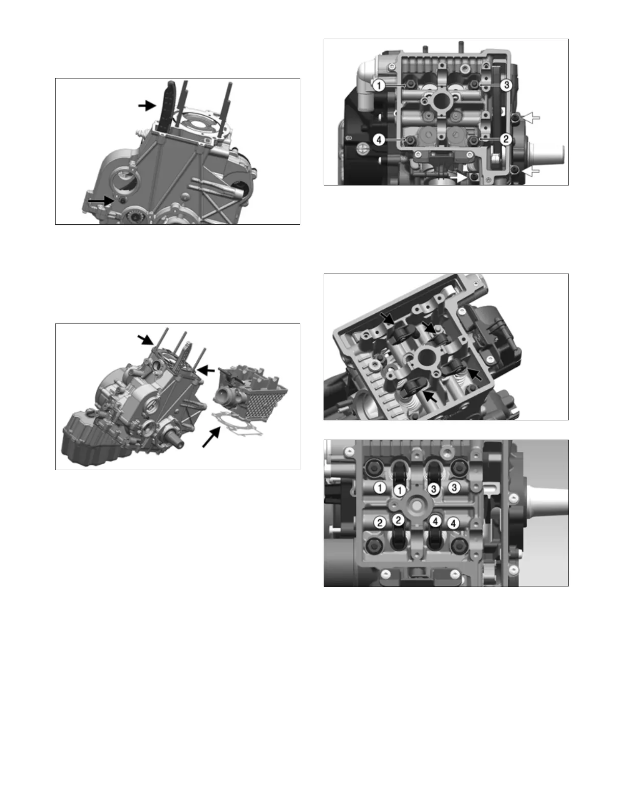
29. Insert two locating pins on top of crankcase. Clean
sealing surface of crankcase and cylinder head and
install a new gasket. Position lower portion of cylin-
der head assembly onto crankcase.
NOTE: The cam bridge and cylinder head are ser-
viced as an assembly.
.
LYC007A
30. Secure lower portion of cylinder head with four
washers and nuts placed on studs. Grease top of
washer with mounting grease being careful not to
grease the threads. Apply Loctite to nut threads. Hand
tighten.
31. Install three outer screws and hand tighten.
32. Tighten four nuts in a crisscross pattern in steps: 88
in-lb (10 N-m); then 22 ft-lb (30 N-m); then a 90°
turn; and finally another 90° turn.
33. Tighten three outer screws to 80 in-lb (9 N-m).
LYC006
34. Oil and replace lifter arms and rocker, matching the
removal marking locations of each on both the cylin-
der head and the rocker/lifter assembly.
NOTE: Rocker and lifters must match up with the
bore and valve as assembled from the factory.
LYC005
LYC005A
35. Insert timing chain into chain housing and wrap
around sprocket on balancer shaft. Use lower crank-
case opening for access to sprocket.
36. To install chain guide rail, insert pin protrusion on
rail into notch in crankcase housing.