54
LYC055
37. Oil camshaft bearing journals in cylinder head, and
place intake and exhaust camshafts in proper loca-
tions. Apply McLube® on cam lobes and axial bear-
ing shoulder of both camshafts. Oil camshaft
journals.
38. Rotate both camshafts into approximately the assem-
bly position.
NOTE: If sprocket is attached to camshaft, remove
sprocket from intake camshaft to make chain installa-
tion easier.
LYC056
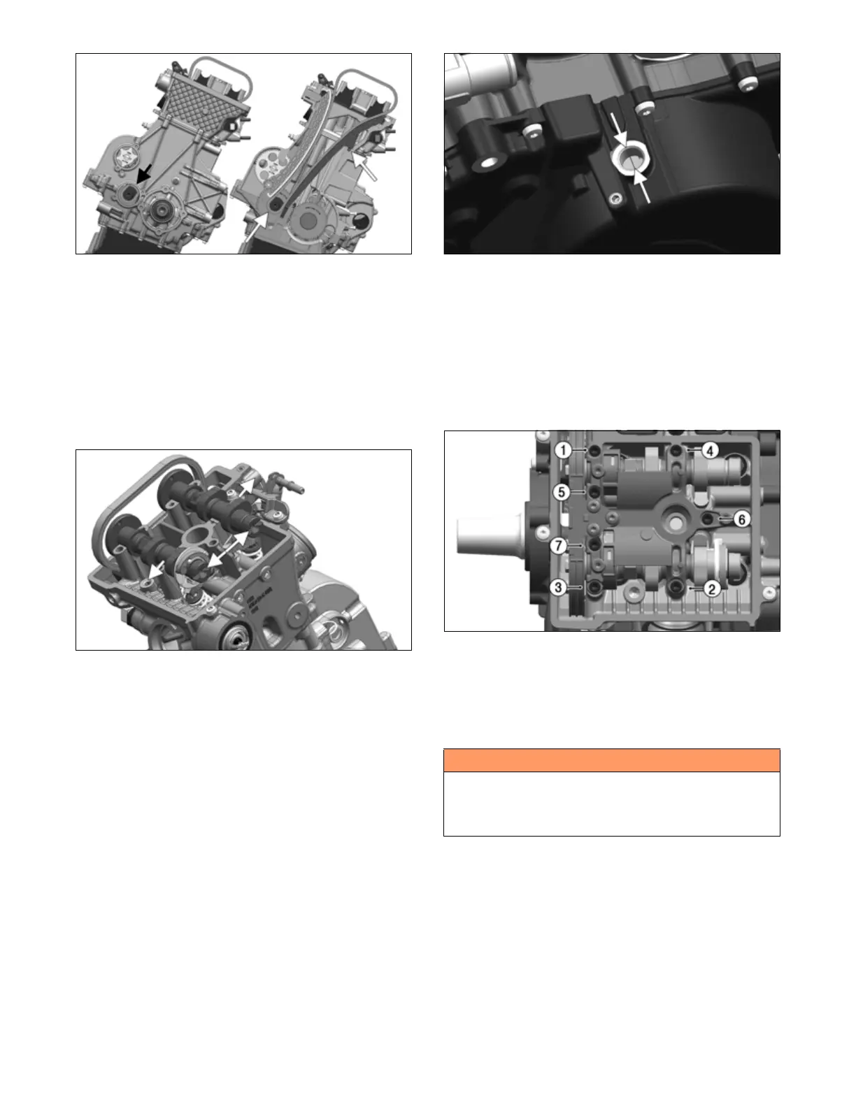
39. Rotate crankshaft in the direction of engine operation
to the top dead center (TDC) position. Verify TDC
by removing the inspection cap from magneto cover.
Align magneto rotor so timing mark is centered in
inspection hole.
NOTE: If there is reason to suspect the engine is not
at TDC, perform a secondary check of TDC through
the spark plug hole.
NOTE: Remove magneto cover to determine the
cause of a misaligned timing mark.
LYC034
40. Install O-ring in spark plug opening on cam bridge.
Position cam bridge carefully over camshafts. Secure
with seven bolts and carefully tighten by hand in pat-
tern illustrated. Tighten to 80 in-lb (9 N-m).
NOTE: Do not allow any misalignment between
cam bridge and cylinder head.
NOTE: Do not allow misalignment of rockers and
lifters while tightening the cam bridge.
LYC039
41. Position camshafts with cam lobes facing away from
each other when slots are in line and insert a tool to
keep them in line.
NOTE: A 6 mm Allen wrench or bar placed between
both camshaft slots will ensure slots are in line.
! WARNING
Camshaft positions are optimized for this engine con-
figuration at the factory. Altering any parts or factory
settings may produce undesirable results and could
void the manufacturer's warranty.