55
LYC035
NOTE: Remove upper chain guard if attached to
cam bridge to make chain installation easier.
42. Set camshaft sprockets in timing chain and lift onto
camshafts. Position each sprocket in the middle posi-
tion of the slotted holes toward the threads in the
camshaft.
43. Alternatively place chain over installed exhaust cam-
shaft sprocket and set intake sprocket in timing chain
and lift onto intake camshaft.
LYC057
44. Snap upper chain guard in sheet metal bracket and
secure to cam bridge with three screws. Tighten to 80
in-lb (9 N-m).
LYC035A
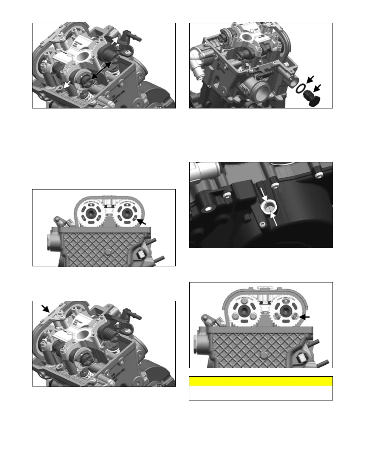
45. Install chain tensioner and new seal ring. Tighten to
50 ft-lb (67.5 N-m).
LYC036
46. Recheck top dead center (TDC) position by remov-
ing inspection cap from magneto cover. Align mag-
neto rotor so timing mark is centered in inspection
hole.
NOTE: Magneto cover may have to be removed to
center timing mark.
LYC034
47. Apply Loctite 272 to six (or three on intake) sprocket
bolts and tighten to 11 ft-lb (15 N-m). Remove tool
from camshaft slots.
LYC058
48. Install fitting (A) on valve cover (if removed) and
secure with circlip. Account for O-ring. Insert valve
cover gasket (C) into valve cover. Position new gas-
ket and cover onto cylinder head.
CAUTION
Failure to perform timing steps could result in piston
damage.