136
OHA096
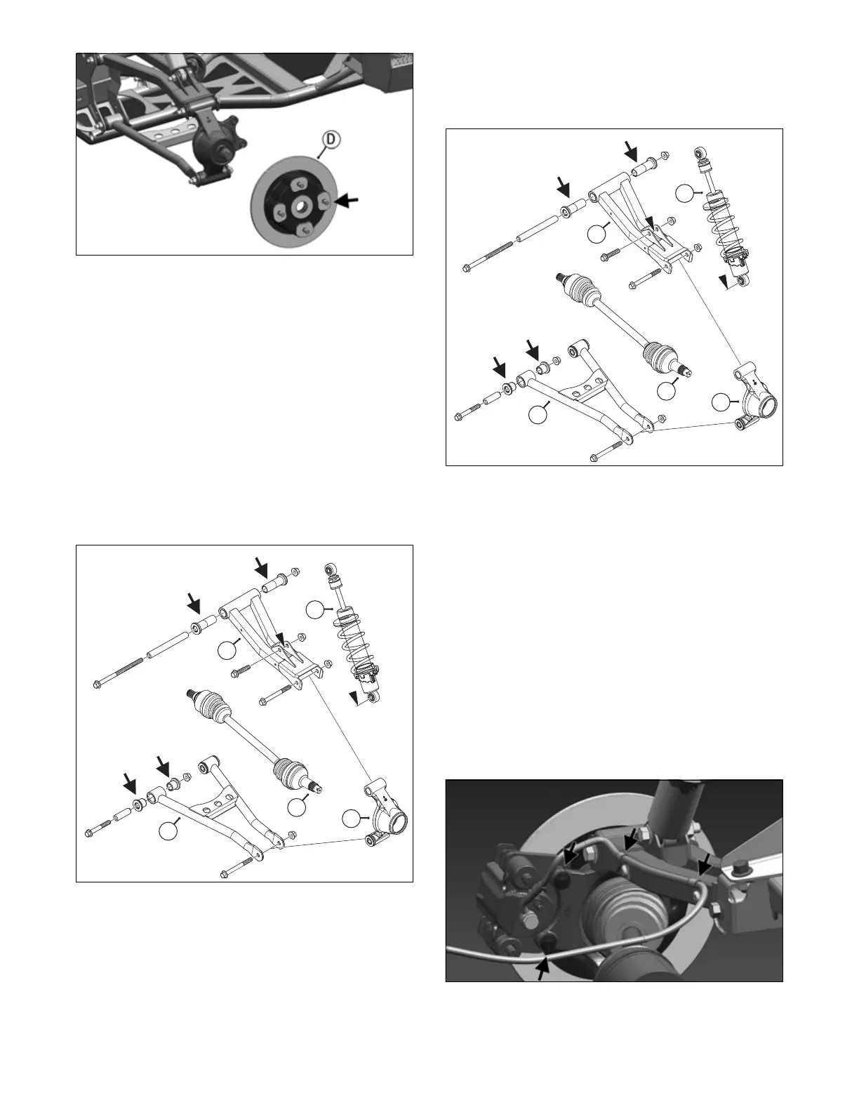
7. Remove the cap screws and lock nuts securing the
knuckle (E) to the upper (F) and lower (G) A-arms.
Discard the lock nuts.
NOTE: Never reuse a lock nut. Once a lock nut has
been removed, it must be replaced with a new lock
nut.
8. Remove the cap screws and lock nuts securing the
shock absorber (H) to the upper A-arm (F); then
move the shock absorber out of the way. Discard the
lock nuts.
9. Remove the cap screws and lock nuts securing the
A-arms to the frame; then remove the A-arms.
10. If being serviced, remove the inserts and sleeve from
the A-arm. Reinstall serviced or new inserts and
sleeve.
OHA094
CLEANING AND INSPECTING
1. Clean all A-arm components using a pressure
washer.
2. Inspect the A-arm for bends, cracks, and worn bush-
ings.
3. Inspect the frame mounts for signs of damage, wear,
or weldment damage.
INSTALLING
1. Install the A-arm assemblies into the frame and
secure with the cap screws and new lock nuts. Only
finger-tighten at this time.
OHA094
2. Slide the knuckle onto the drive axle and into posi-
tion on the A-arms; then secure the knuckle to the
A-arms with cap screws and new lock nuts. Tighten
to 42 ft-lb (56.9 N-m).
3. Tighten the hardware securing the A-arms to the
frame (from step 1) to 42 ft-lb (56.9 N-m).
4. Apply grease on the drive axle splines (I); then
install the hub assembly (D) onto the drive axle.
5. Secure the hub assembly with the nut. Tighten only
until snug.
6. Secure the brake caliper to the knuckle with two new
“patch-lock” cap screws (right side only). Tighten
the caliper to 20 ft-lb (27.1 N-m).
NOTE: Ensure the brake hose is properly routed
and secured to the upper A-arm with the clips tight-
ened to 40 in-lb (4.5 N-m).
OHA092
7. Compress the hand brake lever and engage the brake
lever lock; then tighten the hub nut (from step 5) to
200 ft-lb (271 N-m).