86
CRANKSHAFT POSITION (CKP)
SENSOR
Resistance
1. Set the meter selector to the OHMS position and test
as follows:
2. The meter reading must be within specification.
AC Voltage
NOTE: The battery must be at full charge for these
tests.
1. Set the meter selector to the AC Voltage position and
test as follows:
2. Crank the engine over using the electric starter. The
meter reading must be within specification.
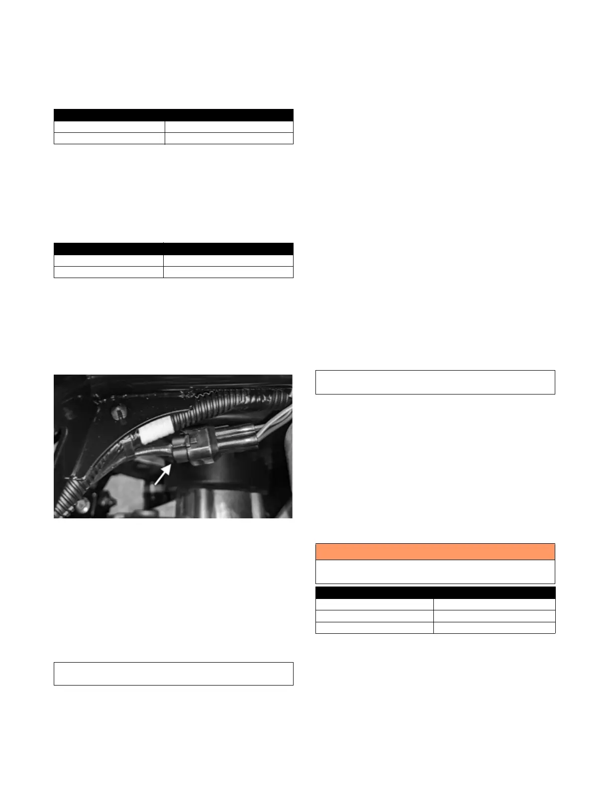
OXYGEN (O2) SENSOR
The sensor is located in the exhaust pipe.
1. Remove the seat. Unplug the connector located on
the rear left side of the ATV.
OHA105
2. On the sensor side of connector, connect the black
(negative) test lead to one white wire pin; then connect
the red (positive) test lead to the other white wire pin.
3. With the meter in the OHMS position, the reading
should be between 6.7-10.1 ohms.
NOTE: If the meter does not read as specified,
replace sensor.
MANIFOLD ABSOLUTE PRESSURE/
INLET AIR TEMPERATURE (MAP/IAT)
SENSOR
NOTE: Preliminary checks may be performed on
this component using the diagnostic mode on the LCD
gauge (see EFI Diagnostic System in this section).
NOTE: The ambient temperature of the engine and
in the intake and exhaust system must be at room
temperature (approximately 68° F/20° C) when per-
forming this test or an incorrect reading will occur.
1. Disconnect the MAP/IAT connector from the sensor
located on top of the throttle body.
2. Select DC Voltage on the tester and turn the ignition
switch to the ON position.
3. Connect the black tester lead to the black/pink wire
and the red tester lead to the orange/blue wire. The
meter should read 4.5-5.5 DC volts. If the meter does
not read as specified, check the ECM connector or
wiring.
4. Connect the MAP/IAT to the harness; then using
MaxiClips, connect the red tester lead to the
brown/white wire and the black tester lead to the
black/pink wire. With the engine running at idle
speed, the meter should read approximately 2.5 DC
volts (MAP sensor signal).
5. Connect the red tester lead to the green/red wire.
With the engine at idle, the meter should read
approximately 2.9 DC volts.
NOTE: If the meter does not read as specified,
replace the sensor.
ENGINE COOLANT TEMPERATURE
(ECT) SENSOR
NOTE: Preliminary checks may be performed on
this component using the diagnostic mode on the LCD
gauge (see EFI Diagnostic System in this section).
1. Connect the meter leads (selector in OHMS position)
to the sensor terminals.
2. Suspend the sensor and a thermometer in a container
of cooking oil; then heat the oil.
NOTE: Neither the sensor nor the thermometer
should be allowed to touch the bottom of the con-
tainer or inaccurate readings will occur. Use wire
holders to suspend the sensor and thermometer.
3. If the readings are not as indicated ± 10%, the sensor
must be replaced.
4. Install the sensor and tighten securely.
5. Connect the leads.
SPEED SENSOR
NOTE: Prior to testing the speed sensor, inspect the
three-wire connector on the speed sensor for contami-
nation, broken pins, and/or corrosion.
WIRE COLOR RESISTANCE
Red to White 200 Ohms
Black to Brown 200 Ohms
WIRE COLOR VOLTAGE
Red to White 2.0 AC Volts
Black to Brown 2.0 AC Volts
Component data can be retrieved using the Dealer
Diagnostic System. Utilize the Sensor Data screen.
Component data can be retrieved using the Dealer
Diagnostic System. Utilize the Sensor Data screen.
! WARNING
Wear insulated gloves and safety glasses. Heated oil
can cause severe burns.
TEMPERATURE RESISTANCE
-20° C (-4° F) 18.8k Ohms
40° C (105° F) 1.14k Ohms
100° C (212° F) 155 Ohms