87
1. Set the meter selector to the DC Voltage position.
2. With appropriate needle adapters on the meter leads,
connect the red tester lead to the orange lead; then
connect the black tester lead to the black lead.
OHA102
3. Turn the ignition switch to the ON position.
4. The meter must show battery voltage.
5. Leave the black tester lead connected; then connect
the red tester lead to the pink/white wire.
6. Slowly move the ATV forward or backward; the
meter must alternate between 0 volts and battery
voltage.
NOTE: If the sensor tests are within specifications,
the LCD gauge must be replaced (see Steer-
ing/Body/Controls).
To replace a speed sensor, use the following procedure:
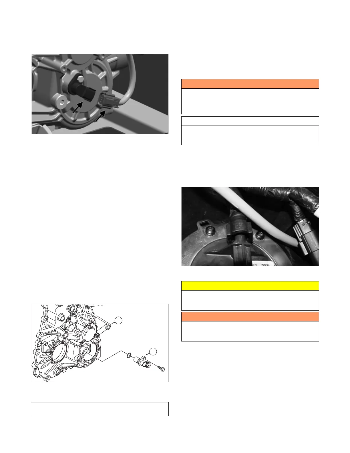
1. Disconnect the three-wire connector from the speed
sensor harness or from the speed sensor (B); then
remove the cap screw securing the sensor to the tran-
saxle (A).
2. Remove the sensor from the sensor housing account-
ing for an O-ring.
3. Install the new speed sensor into the transaxle (A) with
new O-ring lightly coated with multi-purpose grease;
then secure the sensor (B) with the cap screw (threads
coated with blue Loctite 242). Tighten securely.
OHA101
FUEL PUMP/FUEL LEVEL SENSOR
NOTE: Preliminary checks may be performed on
this component using the diagnostic mode on the LCD
gauge (see EFI Diagnostic System in the Electrical
System section).
The electric fuel pump, fuel level sensor, and fuel pump
float are not serviceable components. If any component
fails, it must be replaced.
Testing
1. Blow any debris from the fuel pump connection
using compressed air.
2. Disconnect the quick connect fitting by pushing it
toward the fuel pump fitting; the press the quick con-
nect button(s) and remove the gasline hose.
XR171
3. Install Fuel Pressure Tester in-line between the fuel
pump and the gasline hose.
4. Turn the ignition switch to the ON position. The fuel
pressure should build until the pump shuts off. Pres-
sure should read 3.0 kg-cm
2
(43 psi).
Component data can be retrieved using the Dealer
Diagnostic System. Utilize the Sensor Data screen.
! WARNING
Whenever any maintenance or inspection is made on
the fuel system during which there may be fuel leakage,
there should be no welding, smoking, open flames, etc.,
in the area.
AT THIS POINT
Prior to removing the electric fuel pump, the following
check should be performed to determine that removal
is necessary.
CAUTION
Failure to push the fitting toward the fuel pump will
result in damage to the fitting causing the gasline hose
to be replaced.
! WARNING
Gasoline may be under pressure. Place an absorbent
towel under the connector to absorb any gasoline spray
when disconnecting.