68
3. Inspect the sheaves for any gouges, cracks, or other
damage.
4. Inspect spring for distortion, crystallization, or
breaks.
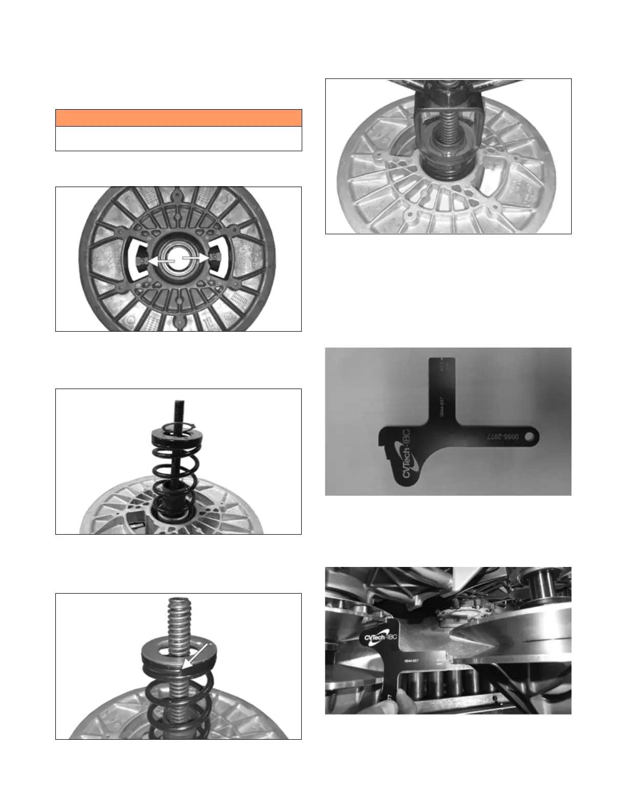
Assembling
1. Install the cam shoes into the movable sheave and
secure using the screws. Tighten securely.
ZR-441
2. Install the movable sheave into the stationary sheave;
then position the spring, spring guide, spring seat,
and the snap ring into the sheave.
ZR-439
NOTE: Make sure the spring guide is orientated to
match with the end of the spring. There should be no
gap between the end of the spring and the guide.
ZR-440
3. Position the snap ring onto the spring seat; then using
the compressor tool, compress the spring until the
snap ring can be installed into the groove in the post.
ZR-442
4. Slowly unthread the compressor tool while aligning
the snap ring with the recessed area in the spring
seat.
DRIVE AND DRIVEN CLUTCH
ALIGNMENT
Check for proper alignment using Clutch Alignment tool
0644-657.
OHA152
1. Align the top notch of the tool with the stationary
sheave of the drive clutch.
2. Use the 43.5 mm alignment mark to the inside mov-
able sheave on the driven clutch.
OHA151
! WARNING
This clutch is under high spring tension. Use caution
when assembling clutch.