Chapter 1 Tracer Summit system overview
4 BMTX-SVN01C-EN
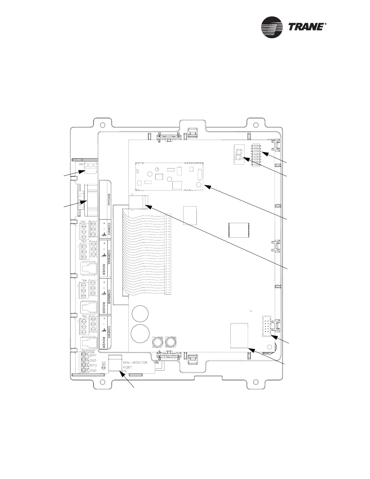
Figure 2 shows the main circuit board and the termination board
installed in the enclosure.
Figure 2. Tracer Summit BMTX BCU board components
Seven-segment
LED display
Modem card
1
(optional)
Modem, phone
line connector
Isolated Comm3
Binary inputs
{
{
{
{
{
Comm4
Comm4
Comm5
Termination board
Main circuit board
EIA-232
BACnet port
Mini-monitor port
Address DIP
switch
1
International installations that have a modem installed must also use a modem shield and cover. For more information, see
Chapter 2, “Modem installation.”
24 Vac power
connector
Operator display
connector
Ethernet connector
 Loading...


