Description of UCM types
BMTX-SVN01C-EN 81
Wiring requirements
To establish wiring connections between the UCM and the BMTX BCU,
refer to the specifications on wire type, topology, and wiring procedures in
“Comm3/Comm4 wiring” on page 35. Attach the communication link wire
to the UPCM at the ICS terminal. Refer to the UPCM installation litera-
ture for connection points.
Device addressing
Each UCM must have a unique address on each link. On the UPCM, the
address is set with the SW1 address DIP switches.
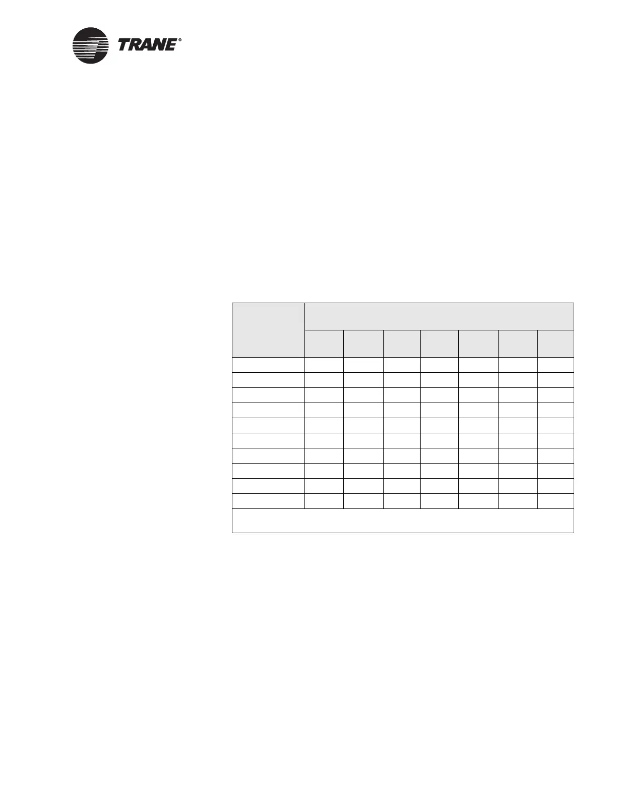
For UPCM DIP switch settings, refer to Table 21 on page 81. DIP switch
settings for BCU addresses 32 through 41 are shown in this table, but you
can place UPCMs anywhere from address 32 to 100.
VariTrane VAV UCMs
The VariTrane variable-air-volume (VAV) UCMs allow a Tracer Summit
system to monitor and control all models of the VariTrane VAV boxes. The
VAV UCMs are referred to as VAV II, VAV III, and VAV IV.
The Comm4 link provides a serial communication interface between the
BCU and each VAV UCM in the system. For specific information about
the number of VAV IIs, IIIs, or IVs allowed per BCU and per communica-
tion link, refer to Table 5 on page 33.
Wiring requirements
To establish wiring connections between the UCMs and the BMTX BCU,
refer to the specifications on wire type, topology, and wiring specifications
Table 21. UPCM address settings
UPCM SW1 DIP switch settings
UCM address 1 2 3 4 5 6 7
32 OFF OFF OFF OFF OFF on OFF
33 on OFF OFF OFF OFF on OFF
34 OFF on OFF OFF OFF on OFF
35 on on OFF OFF OFF on OFF
36 OFF OFF on OFF OFF on OFF
37 on OFF on OFF OFF on OFF
38 OFF on on OFF OFF on OFF
39 on on on OFF OFF on OFF
40 OFF OFF OFF on OFF on OFF
41 on OFF OFF on OFF on OFF
Note:
DIP switch SW1-8 is not used. Set it to the Off position.
 Loading...


